This thread has been locked.

If you have a related question, please click the "Ask a related question" button in the top right corner. The newly created question will be automatically linked to this question.

ADS1298 - 2 of 8 channels work proberly

Other Parts Discussed in Thread: ADS1298

Hi all,

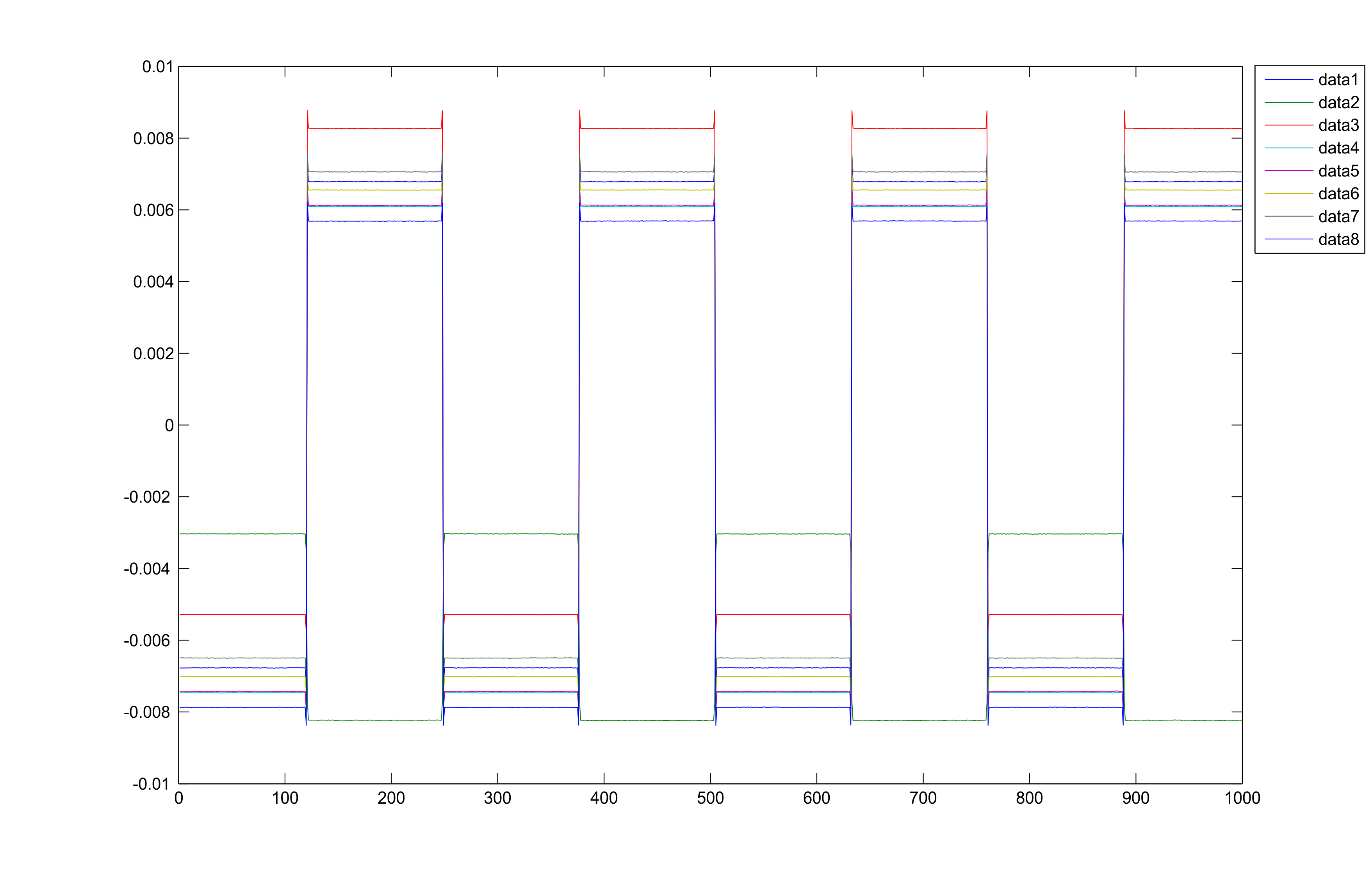
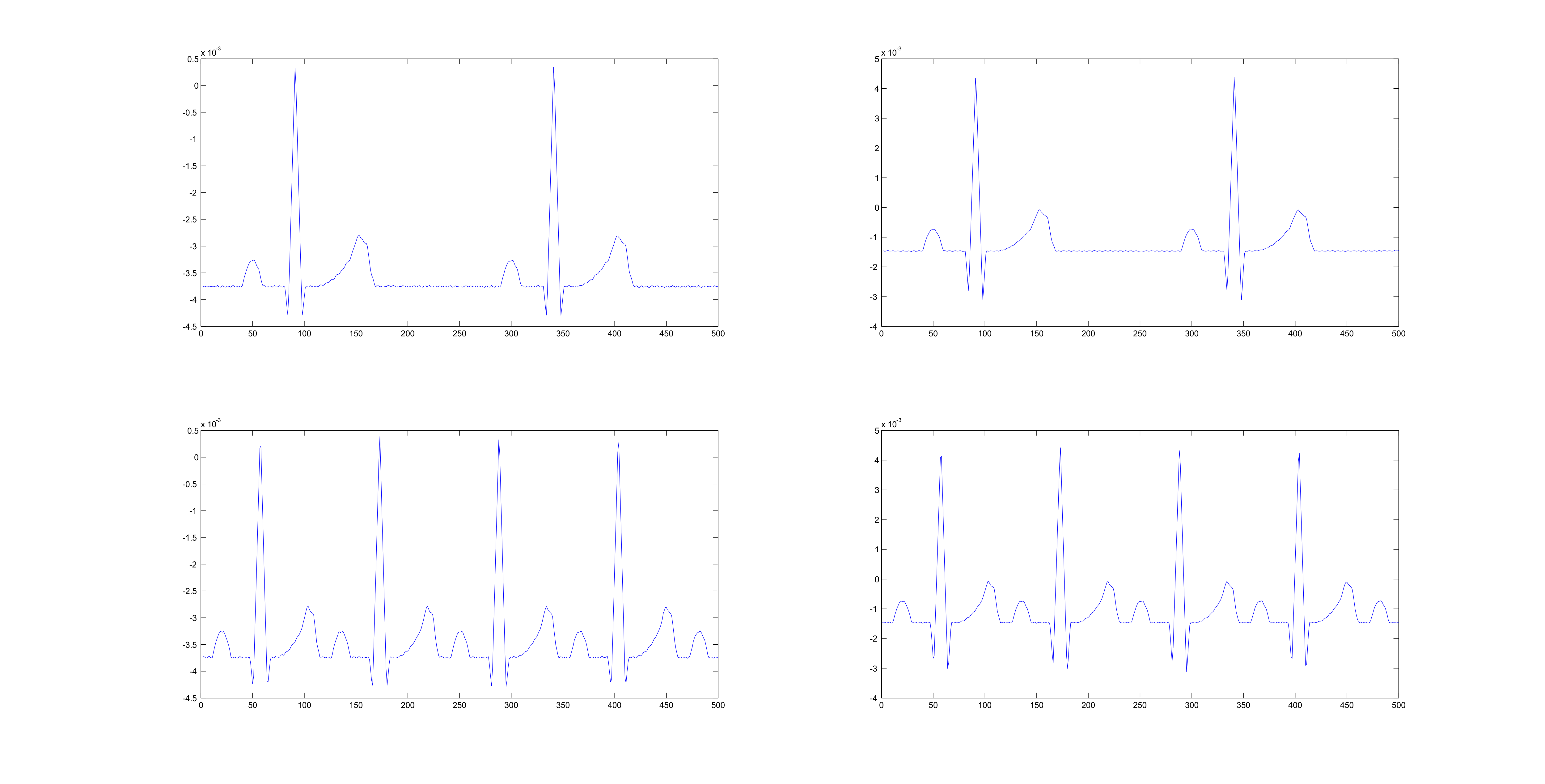
I have a strange problem with ADS1298. When applying a patient simulator to the EVAL Board (in combination with a own dsPIC board), only channels 2 and 3 work proberly (see pic ecg.png - the 1 colum is channel 2, the second colum is channel three). For all other channels (1,4,5,6,7,8) the ADS1298 sends 7F FF FF (which is an overflow) via SPI. The testsignals (see below) are also not bad for all 8 channels.

Information:

all channels are configured for NORMAL INPUT, 500 SPS, HIGH-RESOLUTION

- when attached to the mmb0 board everything is fine.

Registers:

ID 0x92

CONFIG1 0x86

CONFIG2 0x14

CONFIG3 0xDC

LOFF 0x03

all others 0x00 or default value by reset

I am quite sure that I must have done a mistake. But which one? Can anybody help?

Thanks in advance

Bernhard

  • Bernhard -

    It sounds like the WCT is not configured correctly since the channels that display full-scale are the ones that are referenced to WCT.  Channels 2 and 3 are referenced differentially to the electrodes, so this is probably the reason that they read OK.

    I have attached the settings that the ADS1298ECG-FE PDK start-up with, so these should help you get things configured correctly.  WCT1 and WCT2 are probably the best place to start.  Also make sure that J16 (WCT connection to negative inputs) is installed.

  • Greg-

    thanks a lot I will try this today and tell you the result.

    But there is further question on your RegisterMap.txt file:

    Do I always need to configure WCT1 and WCT2 even if I don't want to use Wilson Central Terminal? According to the datasheet it is disabled by default? Or is this just depending on the jumper settings on the EVAL Board (Rev. A), which means it will be possible to use the ADS129x as a normal ADC with differential inputs?

    My application which will use

    Channel 1 for Normal ECG (with RLD) to create a MRI trigger signal on the QRS complex

    Channel 2 will be used for temperature measurement

    Channel 3 will be used for oxygen

    Channel 4 will be used for blood pressure

  • Greg -

    you were right. Now it works with the WCT1 and WCT2 you proposed.Is this offset normal?

    Greetings

    Bernhard

  • Bernhard -

    Even though the electrodes are performing a single-ended measurement, the ADC requires a differential input.  By enabling the WCT, you are connecting the negative input terminal to WCT - essentially the common mode voltage that the patient should be at (is typically done using RLD).  You can turn off the WCT, but then the negative input is floating (as was in your case) - so you would need to connect the terminals to some other voltage that make sense for your system.

    Most EKG applications utilize the connection to the WCT, so unless you are doing something completely different, this is probably the best way to go.

  • Greg-

    thanks. Now I understand. For my understanding it will be possible to turn WCT off as long as I apply a differential signal to the PGA. Is that right?

    Greetings

    Bernhard

  • Yes, you statement is correct.  The input signal needs to be a differential signal - whether it is using WCT or some other bias/signal.

    For your early case, Channel 2 and 3 operated correctly because those are the only two channels that are connected to two electrodes to create the differential signal (Channel 2  = RA-LA, Channel 3 = LL - RA).  All the others had an electrode on positive terminal and negative terminal that was floating (in your case) - therefore the output was overflowing/railing.

  • Greg -

    thanks a lot. At the moment everything works fine with the ADS1298.

    Greetings

    Bernhard