This thread has been locked.

If you have a related question, please click the "Ask a related question" button in the top right corner. The newly created question will be automatically linked to this question.

ADS8556 SPI configuration - control register.

Other Parts Discussed in Thread: TMS320F28335, ADS8556, ADS8568

Hi!

My goal is to set proper data transmission between TMS320F28335 and ADS8556 through the SPI in the Software mode.

The first issue which took me a lot of time is - how to send properly the control register to the ADC?

I read the datasheet (ADS8556 and ADS8568 as well), several posts in TI forum e.g.

http://e2e.ti.com/support/data_converters/precision_data_converters/f/73/p/243723/855496.aspx#855496

http://e2e.ti.com/support/data_converters/precision_data_converters/f/73/p/171174/638950.aspx

The information there were helpful but it seems that I need some help to continue.

Firstly, I am using the eZdsp evaluation board for th DSP. The ADC is soldered on the prototype board. The pins are connected via manufactured made wires.

The configuration of the voltage:

HVSS:  -12V    HVDD: +12V      BVDD: +3.3V        AVDD: +5V

AGND and BGND are connected together.


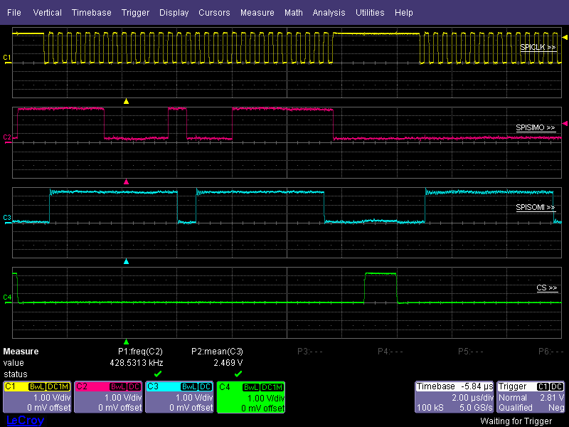
I am trying to send 2 x 16-bits words  0xFE03, 0x07FF (one after another) to the control register but what I receive from the ADC is unclear. The DSP recognizes 0x7FFE on its input of the SPI port.

Here is the screenshot from one of the tests.


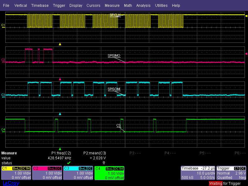
I suppose that the ADC converter should send back the control register but it does not. The question is - why? 

I will be grateful for any suggestions. I will also willingly provide further information about the ADC/DSP configuration if they help to solve this issue.

Regards

Mariusz

  • Hi Mariusz,

    Can you provide a screen shot that is zoomed in a closer?  If you can focus on just the first /CS sequence where you are writing the 0xFE03 and 0x07FF, that would be helpful.  Also, if you have a schematic or a verbal discription that shows/tells how you have the hardware pins terminated, that would be great.

  • Hello Tom

    Thank you for quick response.

    Here is zoomed screen shot of the control register which I try to send to the ADS8556.

    I attached also the pin assignment.

    Is there any reason why does the communication operate in this way? How make it to work properly?

    Regards

    Mariusz

    6567.ADS8556_pin_assignment.xlsx

  • Hi Mariusz,

    I don't see anything in your spreadsheet that would cause the register content not to be sent out of the SDO line.  Can you verify the voltages on the analog and digital power pins, that the RESET pin toggles high to low?  Also please check that the STBY pin is at a valid logic high.  There are a few connections missing that will have an impact on performance (inputs floating, REFC_x floating), but you should still be able to read the registers.

  • Hello Tom

    The voltage levels were correct . In another post I read that toggling RESET pin before sending configuration is desired (at least 50ns up) - that is what I did. The STBY pin (as I wrote in the attached file) was connected to +3,3V (BVDD).

    Finally I was so frustrated that I decided to change ADC converter to ADS 8568. It is much better described (also on the TI forum), so I spend little time to connect it, send configuration and make it work. I also did not connect all pins (CH_xy, REFzP).

    Anyway I still do not know what I did wrong trying to make the ADS8556 work. I found another topic about the ADC where this issue (how to set control register) was still unsolved.

    http://e2e.ti.com/support/data_converters/precision_data_converters/f/73/t/189329.aspx?pi73718=1

    If anyone find similar issue and solution, please share with us in this or in the aforementioned topic. 

    Thank you very much for your efforts!

    Mariusz