This thread has been locked.

If you have a related question, please click the "Ask a related question" button in the top right corner. The newly created question will be automatically linked to this question.

DAC8562 output problem

Other Parts Discussed in Thread: DAC8562

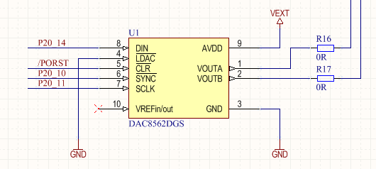
I'm using DAC8562 to generate ramp for VCO. But I encountered some problems with the SPI coding,

I did the power up and internal reference command before sending the data. But didn't see the 2.5V at the VREFIN/VREFOUT pin, and nothing output. Is there any standard process(command sequence) before the data sending?

  • Allen,

    Please share a schematic, the digital words you are writing to the device, and a scope capture of the SPI transaction. These will help me debug your problem.

  • this is the hardware connection, for the code:

    #define CMD_WRITE_IRN ((0x00)<<19) // Write to input register 'n'
    #define CMD_SOFT_LDAC ((0x01)<<19) // Software LDAC, update DAC register 'n'
    #define CMD_WRITE_IRN_UPD ((0x02)<<19) // Write to input register 'n' and update all DAC registers
    #define CMD_WRITE_IRN_UPDN ((0x03)<<19) // Write to input register 'n' and update DAC register 'n'
    #define CMD_DAC_PWR_MODE ((0x04)<<19) // Set DAC power up/down mode
    #define CMD_SOFT_RST ((0x05)<<19) // Software reset
    #define CMD_SET_LDAC ((0x06)<<19) // Set LDAC registers
    #define CMD_SET_IREF ((0x07)<<19) // Enable/disable internal reference

    //for initialize the dac:

    //software reset after power on
    dac_initTxBuffer[0] = CMD_SOFT_RST | 0x1;
    //internal reference enable
    dac_initTxBuffer[1] = CMD_SET_IREF | 0x1;
    //LADC software configure
    dac_initTxBuffer[2] = CMD_SET_LDAC | 0x3;

    send(dac_initTxBuffer);

    for(i=0;i<SPI_BUFFER_SIZE;i++)
    {
    spiTxBuffer[i] = CMD_WRITE_IRN_UPD | ADDR_AB | (i<<4);

    }

    send(spiTxBuffer);

  • one question, if the SYNC signal always stays low, during the data sending status(I need to send thousands of points to generate a ramp, and during this ramp, I always keep SYNC low), is it ok? or it should be  high after each command and low again for next command?

  • Hi Kevin,

    The scope that I'm using have some problem with the output, but it's almost the same as this one in picture, but with 24 clocks for each command, and slaveoutput is always low during the BUFFER_SIZE of commands. http://e2e.ti.com/support/data_converters/precision_data_converters/f/73/t/253249.aspx,

  • Hi Kevin, this is the 

    probe1: Data in

    probe2: Clock

    probe3: SYNC(slave selection)

  • Allen,

    In this case SYNC behaves more like a frame sync signal than a chip-select or slave-select signal. It is required to terminate each frame that is written to the device. 

    The Serial Interface section of the DAC8562 datasheet mentions the following:

    "The write sequence begins by bringing the SYNC line low. Data from the DIN line are clocked into the 24-bit shift register on each falling edge of SCLK. The serial clock frequency can be as high as 50 MHz, making the DAC756x, DAC816x, and DAC856x compatible with high-speed DSPs. On the 24th falling edge of the serial clock, the last data bit is clocked into the shift register and the shift register locks. Further clocking does not change the shift register data."


  • Hi Kevin,

    Yes, you are right.

    Thanks for your help!