A related question is a question created from another question. When the related question is created, it will be automatically linked to the original question.
If you have a related question, please click the "Ask a related question" button in the top right corner. The newly created question will be automatically linked to this question.
I would make certain that pin12 (SPI/I2C) pin is "low" enabling I2C mode. If A0/A1/A2 are ground, then the slave address will be the 7bit binary 1100001.
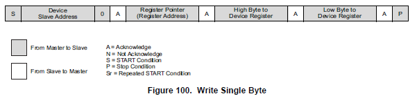
I've copied an image for an I2C write below. More information can be obtained from pg.51 of AMC7812 ds.
The following is an I2C Write sequence.
1. The master device asserts a start condition.
2. The master then sends the 7-bit AMC7812 slave address followed by a zero for the direction bit, indicating a write operation. Note that the correct slave address is 0xC2 (11000010)
Slave address (0xC2 - write) (0xC3-read)
3. The AMC7812 asserts an acknowledge signal on SDA.
4. The master sends a register address.
5. The AMC7812 asserts an acknowledge signal on SDA.
6. The master sends a data byte of the high byte of the register (D15:D8).
7. The AMC7812 asserts an acknowledge signal on SDA.
8. The master sends a data byte of the low byte of the register (D7:D0).
9. The AMC7812 asserts an acknowledge signal on SDA.
10. The master asserts a stop condition to end the transaction.
I also have problem to access an AMC7812 through the I2C bus.
We mounted that chip on a custom board, following your application design.
The slave address is set to 0x2f (A0, A1 and A2 all to Vdd), pin 12 is directly connected to ground, SDA and SCL are pulled up to Vdd through two 10k resistences.
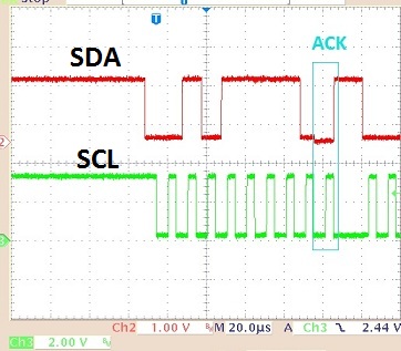
The master sends the 7-bits slave address, followed by a 0 (for writing), then switch SDA direction to receive the ACK from the slave, but the slave doesn't send the ACK.
I'm sure (checked by an oscilloscope) that all the timings fall into the Standard mode (100 kHz max clock).
I tested several boards
What can I do now? Have you any suggestion?
I could send you, on your request, an image of the timing diagram captured from the oscilloscope.
Have you verified pin12 is connected to ground, enabling I2C mode. I also wanted to verify that the 7-bit slave address you are using is: 0101111. A snapshot of the oscilloscope capture will be very helpful for debug.
The datasheet indicates that when A0, A1 and A2 are pulled high, the 7-bit slave address is: 0101111.
To perform a write, a '0' must be appended to the right of the above 7-bit address, therefore altering our slave address to 01011110 (0x5E). The write '0' or read '1' bit is the LSB of the Slave address byte.
I suspect you didn't receive my mails in reply, so I'm replicating them here, because this point is quite urgent for us: we are developing a new hardware board, so we must decide quickly whether we can include the AMC7812 in the board or choose another solution, even different from TI.
Pin 12 is directly connected to ground, verified both by oscilloscope and ohmmeter, address pins A0, A1 and A2 are connected to Vdd through 0 Ohm resistors.
My i2c driver automatically takes the 7-bits slave address then append a ‘0’ for write operations and a ‘1’ for read operations. So, the 8-bits addresses sent are 0x5e for write and 0x5f for read.
I also tried to send messages to all the possible i2c addresses for AMC7812, just to check if something is wrong on our hardware, but the result is the same: no ACK.
I can’t get the ACK since when the master sends the slave address.
Thank you for the post. As you suspected, I did not receive any email regarding the question. I've tried to recreate the problem in the lab, but unfortunately wasn't able to. I've included the pictures of the successful captures. From the oscilloscope picture you have provided, the only thing that looks out of place is the SCL dip before the START condition, this may affect the transaction. Have you verified the Master SDA output is in a high impedance state when waiting for the ACK? Can you also post the supply voltages for AVDD, AVCC, and DVDD.
Thank you for your reply, I would like to have the same picture on my oscilloscope...
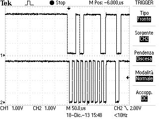
In the past days I fixed my I2C driver, to eliminate the extra dip of the clock (I also noticed it) and some glitches I have around.
So, the situation is that the trace I get is "clean", as you can see below:
Unfortunately, I still can't get the ACK.
HIgh impedance:
I'm reasonably sure that the SDA line stays in high impedance between a stop and a start (really the master "takes" the line some microseconds before the start and "releases" the line some microseconds after the stop), and when is the moment to receive the ACK. I have another I2C device on the same bus, and the master can communicate to it without problem. Just for testing, I removed the second device from the bus by cutting its SCL and SDA pins, but nothing changed for AMC7812 (the picture above was captured in that environment).
Voltages (in parenthesis values measured by a digital voltmeter):
AVCC1 = AVCC2 = 10 V (9.99)
AVDD1 = AVDD2 = 5 V (4.94)
DVDD = 5 V (4.95)
IOVDD = 3.3 V (3.32)
If it can help you, the chip mounted on the board I'm testing is marked as below:
1st row: (TI logo) 21A1L8WG4
2nd row: AMC7812
I also tested two other boards, both with an AMC7812 chip reporting "28A38GWG4" on the 1st row.
Thanks for the updated capture. The capture looks fine, as nothings seems to be visually wrong with the I2C transaction. I'll look into the AMC7812 device numbers that you have supplied. In the meantime, can you supply a schematic that I can cross check with our EVM?
Thanks again,
Matt
- I have updated this post with a schematic for the current AMC7812EVM.
I've cross checked the schematic with our EVM schematic, and everything looks like it should check out. Are you using any external circuitry to regulate the supplies, or are you using a power supply for test?
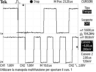
As stated previously, the I2C transaction looks visually correct, but it would be a good idea to check it against the timing parameters specified in the AMC7812 datasheet (pg 10), more specifically the T(hd,sta) parameter.
For a start condition, the time between the falling edge of SDA and the falling edge of SCL is at least 8 us; in the picture below you can read 9.6 us:
For a sto condition, the time between the rising edge of SCL and the rising edge od SDA is at least 8us; in the picture below you can read 8.8 us:
Currently my driver is exceptionally slow, but this complies with standard mode Thd,sta (min 4.7 us) and Tsu,sto (min 4 us).
The power supply circuitry is on the board itself and provides all the voltage needed (1.8 V, 3.3 V, 5 V, 10 V).
It may be a good idea to verify that the power supply circuitry is capable of driving the device with these voltages. The datasheet specifies a maximum current requirement of 12.5mA for both AVdd and DVdd, this value does not include any load current drawn from DAC outputs, so a power supply with capable overhead should be implemented. It may also be worthwhile to retry the experiment with power supply equipment.
Some I2C drivers follow a bit banging scheme and drive data (IO set as output), but it should be verified that they do release the line and switch to a high impedance state, usually an IO change to input, before the ACK.
The power supply circuitry on our board is capable of up to 1 A for each voltage supplied.
As I told you in a previous post, I'm quite sure that the line goes to high impedance while waiting the ACK (the pin of the master is switched to input, and it is an open-drain stage).
One question: on our board we connected the Power Pad of the chip to ground: could it be a problem?
I think that a test we can run to get out of this impasse could be connecting the I2C bus of our master directly to an Evaluation Board: can you supply one to us?
We will be in holydays for Christmas until next January 6; I can read your mails and posts, but I'll be able to run tests only after the holydays.
Thank you for your help and Merry Christmas to you and your team.
On a different note, a colleague of mine looked over the schematic and found a few possible mistakes. Currently, Q14 and Q19 of the schematic show to have a floating base and, as a result, will not work for remote measurement. To correct, both transistors should have a short connection from base to collector. An example of this connection is found in the EVM schematic attached to an above post.
I’ll also be out of office next week for the holidays, and will be back during the first week of the New Year. Thank you for the Holiday wishes and have a Merry Christmas and a happy New Year.
Your schematic shows to have the Reset pin pulled to IOVDD, but it may be a good idea to inspect the state of the pin/signal during the I2C transaction. It is usually the simple things we tend to overlook.
Ok, just because that's a thing we could overlook, it was the first thing I watched: I haven't a picture from oscilloscope, but the reset pin is set to IOVDD during the transitions.
Ok, at the moment we will put a piece of wire from base to collector of both, and we will correct the mistake in the final version of the board. Thank you very much for the info.
About your last request, our mailing address is:
Radio Activity srl Via De Notaris 50 20128 Milano MI ITALY
We just received the EVM board (AMC7812EVM-PDK). Unfortunately there isn't documentation inside, but we found it on TI web site. There is still a problem: as stated in the on-line documentation, we could download a program/driver for the board (which has an USB plug) from this link:
Apparently there is some problem with the TI External ftp website. We are currently trying to get IT involved, and will hopefully have a solution soon. I'll update this post if I find more information on the problem.
Can you please try to download the software again, I think the ftp issue may have been resolved. Please let us know if you still receive the error message.
First of all, we could download the software for the EVM, so we could test the EVM and watch it works fine.
Then we connected the I2C bus of our board to the EVM, and all was working well. This means that our I2C driver and bus is ok.
Then we supplied the EVM by the voltages supplied in our board, and could reproduce the problem!
After some checks we discovered that (this is the key point) without AVCC (mean AVCC=0) the Communication Interface of AMC7812 doesn't work at all!
In our board, the voltage source which AVCC is connected to also supplies a number of TLV320 used for audio paths and is controlled by a specific on-board device; when starting the application software, that device initializes before issuing that voltage, but this takes some time (seconds) to be completed.
Unfortunately, there isn't in the AMC7812 Data Sheet any point stating that without AVCC the Communication Interface is off, so the task for AMC7812 (intentionally) at first deasserted the reset, then tried to initialize the internal registers, then waited for the setup completion of the whole board before starting its work: the registers initialization of the AMC7812 took place when AVCC was still off, so it couldn't happen! After some failed attempts, the task signaled a critical error and caused a software restart.
Now in the application task, once the board setup has completed (and AVCC is present), we could initialize the device and start its work.
I think this problem is now solved. Thank you for your time and cooperation.