


Hi all,
We have designed a RTD measurement system, using 24 bit ADC ADS1248 from TI.
We are measuring different RTD types like Pt100, Ni100, Pt200 , Pt1000 etc. Maximum resistance we need to measure is around 3.9KΩ. Thus we have used a high precision 4.3KΩ as RREF & IDAC out to be 500uA in our design.
Below is the snapshot of the RTD measurement section of the schematics.
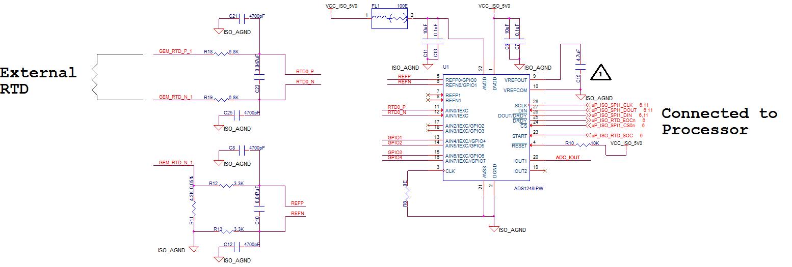
We are able to measure the resistance & calculate the temperature as expected using the above design.We are calibrating the entire system at the beginning. We are achieving good accuracy with this method.
Only issue we are facing is with respect to the accuracy of measurement during a long run. If we connect a constant resistance for a long period of time, we are observing significant variation in the ADC readings.
For example, we are simulating a constant resistance of 3901.9Ω using a RTD simulator. If we keep our system running with this resistor for 15 hours we are observing around 3Ω variations. This corresponds to around 1°C variation with respect to Pt1000 RTD.
Below is the plot of variation in°C with respect to time.

RTD simulator we are using is having a accuracy of 0.4Ω. We are not able to find out the reason for 3Ω variations in reading over the long run.
Is there anything we can change in our design to avoid this variation ? Please suggest.
Thanks,
Suresha N S


