This thread has been locked.

If you have a related question, please click the "Ask a related question" button in the top right corner. The newly created question will be automatically linked to this question.

noise on "ADS1248"

Other Parts Discussed in Thread: ADS1248

Hello

I designed a board 4 mounts ago, it works good in almost all condition. but i  have a problem in 1 condition. my board can calculate TC (J or K) and PT100 simultaneously.

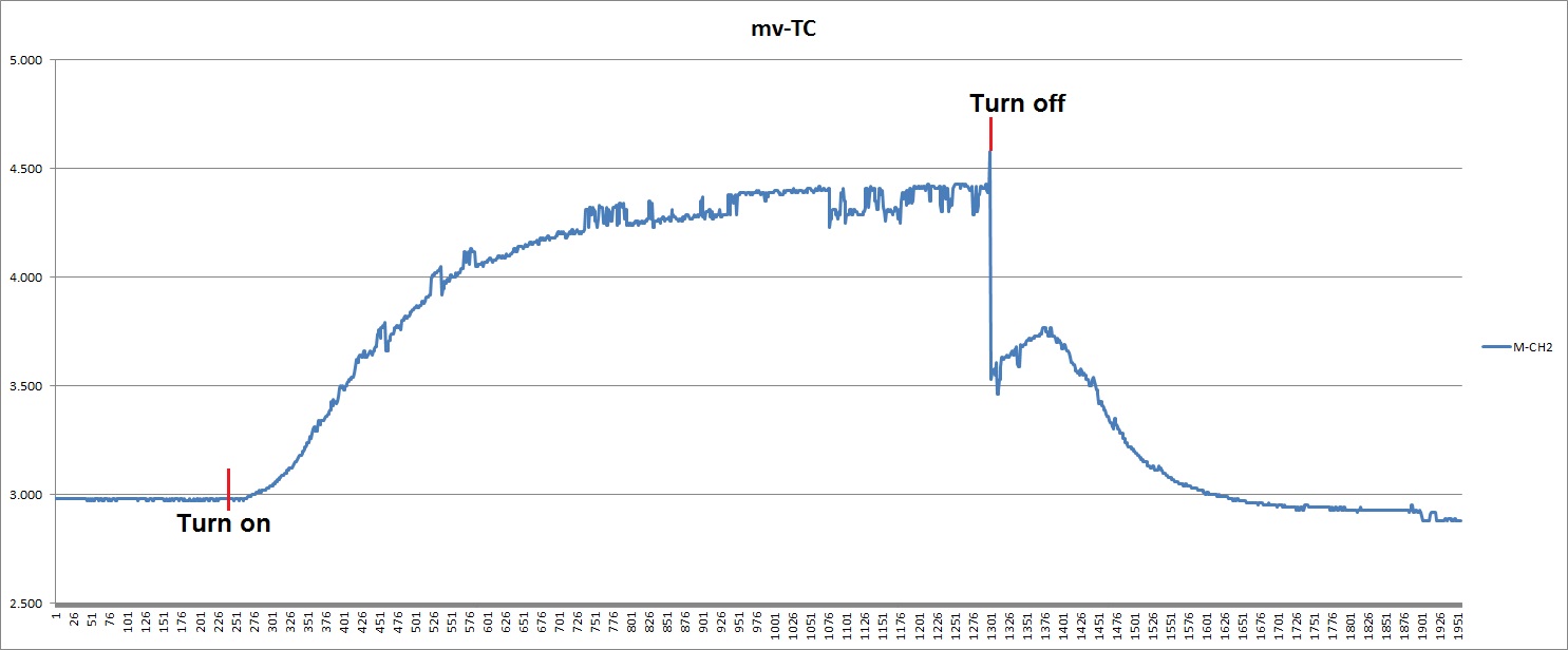
the problem is: if near my board a relay turn on the value of temperature (TC or RTD) get an offset, the value of temperature slowly get rise and if the relay turn off the value suddenly go back to its correct value!

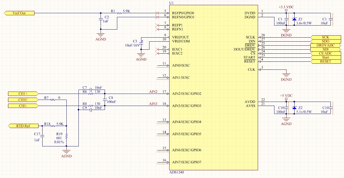
my schematic is like bellow

the adjustment of ADS1248 is:

    if ( RTDorTC[ 0] == 0)    {                //Thermocouple
        _ADS1248_REG.MUX0._MUX0     = 0b00010011;
        _ADS1248_REG.VBIAS._VBIAS     = 0b00001000;
        _ADS1248_REG.MUX1._MUX1     = 0x30;
        _ADS1248_REG.SYS0._SYS0     = 0x10;        //PGA = 32, DOR = 5 SPS
        _ADS1248_REG.IDAC0._IDAC0     = 0x00;
        _ADS1248_REG.IDAC1._IDAC1     = 0b11111111;
    }

    if ( RTDorTC[ 0] == 1)    {                //RTD
        _ADS1248_REG.MUX0._MUX0     = 0b00010011;
        _ADS1248_REG.VBIAS._VBIAS     = 0x00;
        _ADS1248_REG.MUX1._MUX1     = 0x30;        //0x20
        _ADS1248_REG.SYS0._SYS0     = 0x20;        //PGA = 2, DOR = 5 SPS
        _ADS1248_REG.IDAC0._IDAC0     = 0x07;
        _ADS1248_REG.IDAC1._IDAC1     = 0b00100011;
    }

in this 4 mounts i test everything but i can't do anythings.  i think that this noise is related to ADS1248.

can anybody help me.

  • Hi Mahdi,


    My first guess would be that you are having a problem with EMI coming from the relay. You might be able to test this to see if shielding the board in a completely enclosed metal box like a faraday cage helps with this, or if placement of the board further away from the relay helps as well.

    How much does the ADC output change with the use of the relay? I want to know how many counts this is, and how much voltage this is equivalent to. If you move it further away from the relay what is the change in the reading? If you isolate the board in a metal box, what is the change in the reading? I'd also like to know how it is changing. Is it a momentary change in the reading, or does it have a long time constant.

    Another question I had was, what are you using the relay for? Is it in the signal path? The relay itself can have a thermocouple component and cause added voltage in the measurement. What brand and model of relay is it? If it is in the signal path, some manufacturers will list the thermocouple voltage change in the datasheet.

    Also is this a latching relay? The latching relay may have less of an effect because it requires no power to maintain contact closure and therefore no EMI.

    There are quite a few questions in this post. Reply to the post when you are ready.


    Joseph Wu
  • Mahdi,


    I also meant to add that If there is EMI, it's important to close some of the electrical loops in the circuit. Long wires can pick up more EMI so you want to make the loops smaller by shortening wires and twisting long lengths together to reduce the loop area. This is most important along lengths of wire on the input and on the reference, but can be many places within the circuit.


    Joseph Wu
  • Dear Joseph,

    Thank you for your answer.

    i do what you said. i folded my board in an aluminum foil an repeat my test. we haven't any problem. i mean the temperature doesn't have any offset because of the relay.

    i also should say that the relay is not on my board, it is just near my board.

    i provide some data when we don't use any metal box that i want you to know. in my test i use the temperature calibrator "PSIP 714",i connect the calibrator to my board and set it to 100 ⁰c. after a while i turn on the relay and then off. the below chart show the mv i measured. cold junction is about 30⁰c

    but now, i know the reason of this, 'EMI" effect

    can you give me some document for this topic. in my PCB i design good AGND and DGND. how can i reduce/omit the EMI effect on my board?

    tanks a lot,

    best regard

    Mahdi.

  • Mahdi,


    There are quite a few things you can find about EMI if you google it. Here's a presentation about PCB layout techniques and reducing EMI:
    http://www.ti.com/lit/an/szza009/szza009.pdf

    I found another blog about relay drivers and EMI:
    http://e2e.ti.com/blogs_/b/analogwire/archive/2013/11/15/4-steps-to-reduce-emi-when-designing-with-darlington-relay-drivers

    I do know of another presentation that TI put together. I'll look for it tomorrow and post it when I find it.


    Joseph Wu
  • Dear Joseph,

    Thank you for your answer.

    tanks a lot
    best regard
    mahdi
  • Mahdi,

    EMI in Prec Linear Circuits_040214.pdf

    This was the presentation that I was looking for. It's for linear circuits, such as amplifiers but many of the concerns are the same for data converters.

    Joseph Wu

  • Dear Joseph,

    Thank you for your answer.

    i study the presentation, i think this can solve my problem.
    but for testing any action on this way i need time. i will send you the result as soon as possible.

    again i want to appreciate you, because of your answer.
    best regard.
    mahdi