This thread has been locked.

If you have a related question, please click the "Ask a related question" button in the top right corner. The newly created question will be automatically linked to this question.

ADS7825 internal operation _additionary

Other Parts Discussed in Thread: ADS7825


Dear Mr Harsha-san

Hello,

Please allow me to have questions in place of Seishin ( My colleague) because he cought a cold today.

Thank you for your answer to seishin !

I would like to have additional questions in addition to Seishin's thread

http://e2e.ti.com/support/data_converters/precision_data_converters/f/73/p/395116/1399634#1399634 


----------------------------------------------------

# Question1 


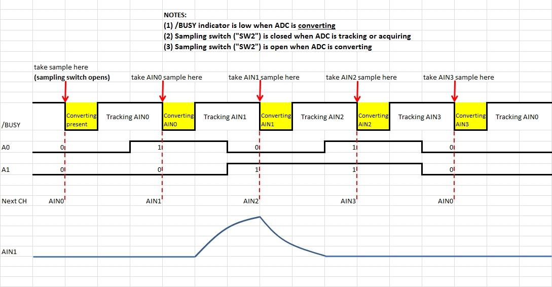
Is the timing diagram in attached sheet ( my understanding)  correct?  ( Thank you for your answer to seishin) 
                    
# Question2 


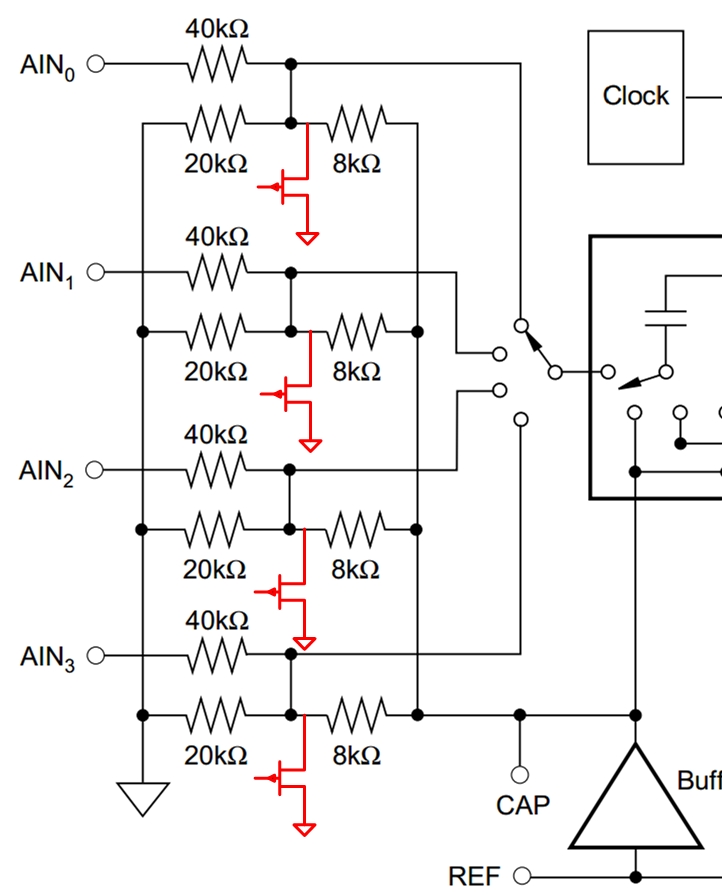
My understanding is CDAC acquire the analog voltage of AIN1 when SW1=SW2=AIN1.

In this time, customer's concern is voltage rise depend on input cap..

ADS7825 acquire the voltage just at the edge of BUSY goes UP? (  My hope is , there are

No concern about the A/D conversion result even though we can see the rise of analog voltage .....  Is it correct?)
                            

#Question3


From Customer's test result, AIN1 analog voltage start to fall to 62mV ( seishin's thread) when they had selct AIN2.

In this time, SW1/SW2 swtitches  from AIN1 to AIN2.  Here is the question. 


Don't you have any additional switch (SW_x) who discharges the parastinc cap to ground   in front of the SW1 ,, do you ??

---------------------------------------------------------------------------------------

Our cusomer had using TI/BB products long time ( and will be), but they ahd jut found out the phenomenon in their circuit.

They want to fix  the problem but they want to know the internal mechanism to  estimate  their workaround is correct or not by themselves.

Our customer is so in hurry , so , please adivse me  if available, tommorow, hope to within 2days....

Please allow us such a complicated issue..

Best Regards


ADS7825_Mechanism.pdf


  • Hello Shibatani-san,

    Q1) Your understanding of the timing diagram is more or less correct, but I would like to emphasize a couple of important details that might help clarify the operation of the part:

    Q2) The ADS7825 starts acquiring when SW1 and SW2 are closed. The voltage across the sampling capacitor tracks the input voltage as long as the switches remain closed. At the end of the sampling window, the sampling switch opens and the voltage on the sampling capacitor is then converted by the ADC. So the input sample to be converted is acquired just before the falling edge of /BUSY when conversion begins.

    The 30mV rise at the input will cause the ADC output to increase proportionally (by approximately 750 to 800 codes). Given the long rise time it appears that the customer may be floating AIN1. To what value does AIN1 settle if the input channel is not changed?

    Q3) I was able to find partial schematics of the ADS7825 input circuit and you are correct - there is an active pull-down to GND on each of the input lines:

    It appears that under normal operating conditions, the inactive channels are pulled down to ground which would explain why AIN1 approaches 0V when AIN2 address is latched. What is the customer measuring on AIN0 and AIN3 when AIN2 is addressed? 

    Best Regards,

    Harsha


  • Dear Harsha-san,

    Thank you very much for your quick answer !!!

    I appreciate that.

    As per your advise, I will ask customer but  please give me time to  customer to have input voltage capture not only AIN1, but also AIN0 and another channel.

    Anyway, please let me ask you again  to confirm..

    Sorry that bother you  such complicated question again....

    Q1  My understanding is , ADS7825 samples the analog voltage to sampling cap ( MSB's cap like as sbaa043.pdf )

           just at the rising edge of BUSY,,,,, is  it wrong? ... see atached fille

          The reason why of this question is, customer says their ADC converted result looks correct, even though there are voltage rise of

          30mV ...

          Customer settle  AIN1 voltage approx a few mV  from opeamp ,R=100hm/C=0.1u  to AIN1. ( not open ), and they say conversion result seems correct..

          If ADS7825 samples the analog voltage as your point described  ' take AIN1 sample here ', conversion data should be 30mV( in case with 0.1uF at

          the AIN1 terminal, not floating.) as you fugured out 50-800codes.

    Q2  Customer says that the voltage rise  is big when the time  between conversion from previous/next is long ..... 'tx'   attached file,

           Also, data sheet page7 says ' 25us ' for throughput assures accurate acquisition'.

           I think customer should use large input cap  and also should keep this within 25us  if they insists the voltage rise. ... Is it wrong?

      with my best regards

      Hope to your answer on Monday .


  • Hello Shibatani-san,

    I apologize for the delay in my response. After our last correspondence I decided to put together a test setup to verify the functionality of the ADS7825. That took some time but the test results confirm that the ADS7825 behaves almost exactly as I have described to you. Here are my observations:

    - Upon power-up, the input channel corresponding to the prevailing [A0, A1] setting is selected

    - The selected input channel (summing node before switch) is internally pulled up to 1.79V and all other channels are pulled down to about 50mV (you cannot sense the internal summing nodes unless the AIN* pins are left floating)

    - When a convert signal is issued, the ADC takes a sample of the selected input channel (sampling switch opens) on the falling edge of /BUSY and starts converting it

    - The falling edge of /BUSY is also used to latch the address of the input channel to be selected for sampling on the next rising edge of /BUSY

    - During conversion (while /BUSY is low), *all* input channels (summing nodes before switch) are internally pulled down to GND

    - When /BUSY goes HIGH, the ADC starts acquiring the input channel corresponding to the value stored in the address register

    Please see the attached file for actual test data.

    With regard to your question relating to SBAA043, once again the description of the sampling process is consistent with my explanation - a sample is taken only when the sampling switch opens at which point the voltage across the sampling capacitor becomes constant. This is the voltage that is then converted by the ADC. Please see excerpt below from SBAA043:

    The only difference between the ADS7825 and the ADS574 is that the sampling switch opens on the rising edge of STATUS on the ADS574 but on the falling edge of /BUSY on the ADS7825.

    Best Regards,

    Harsha

    ADS7825operation.docx

  • Hello Shibatani-san,

    I just wanted to follow up with you on your investigation. Have there been any new developments? Have you had a chance to review the test data I sent you? I noticed that you have started another thread with similar questions:

    http://e2e.ti.com/support/data_converters/precision_data_converters/f/73/t/397847

    I would like to share with you the results of experiments that I performed to demonstrate a couple of key behaviors of the ADS7825 that have repeatedly come into question. In particular, I wanted to prove that the ADS7825 takes a sample of the input voltage on the falling edge of /BUSY and not the rising edge. I also wanted to demonstrate how channel selection works. Procedural details, test conditions and test results are documented in the attached file. 

    These experiments are simple and I would recommend these to the customer to confirm that the behavior of the ADS7825 in the end-application is consistent with the datasheet.

    Please go through the document and let me know if I can assist you further. Thank you.

    Best Regards,

    Harsha

    ADS7825_sampling_channelSelection.docx

  • Dear Harsha-san,Thank you very much on your advice on 30-Jan .
    I understood and I will talk to customer.
    Thank you for your support for long time.