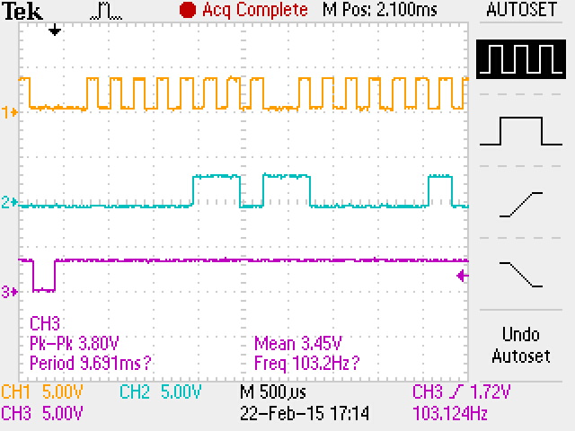
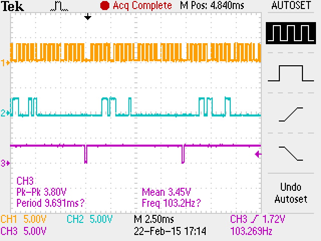
Attached are screenshots from the oscilloscope showing the SPI lines to a ADS8881 ADC with the bus running at 5000 Hz. Channel 1 is the SCLK, channel 2 is the data returned from the ADC, and channel 3 is the CS which is connected to the ADC's CONVST in a Daisy Chain config with 1 ADC (prototyping for future bus expansion).
As I understand it, the ADC should return 18 bits, MSB first. The two least significant bits in the first byte transmitting should be polarity bits, 01 for positive, 10 and 11 for negative according to the transfer function chart supplied in the data sheet. However, the ADC appears to only respond with two bytes of data that, when converted, correspond to the sample voltage.
My question is, why is the ADC not appearing to return 18 bits, and instead return 16 bits? Am I misunderstanding something?
Thanks in advance.