This thread has been locked.

If you have a related question, please click the "Ask a related question" button in the top right corner. The newly created question will be automatically linked to this question.

ADS1248 data read problem

Other Parts Discussed in Thread: ADS1248

Hello,

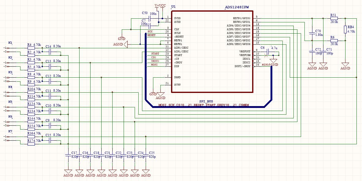
I have an application for measuring temperature using ADS1248 and 2-wire connection of Pt1000 sensors. The schema is in the first picture bellow. For controll the ADS1248 chip I am using ATmega8 microcontroller.

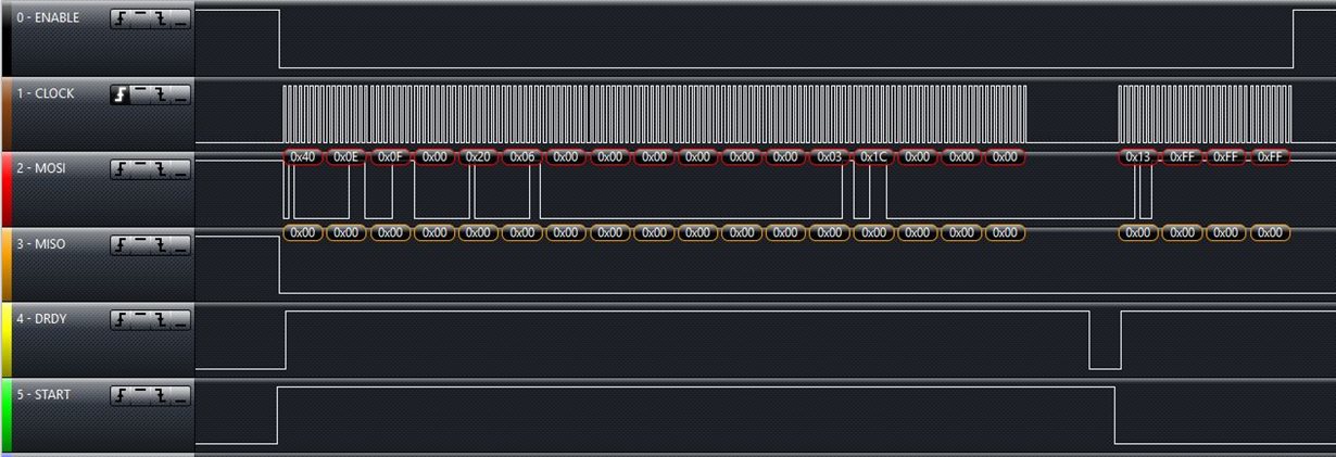
I am able to write (WREG) and read (RREG) a configuration registers. Now I have connected two Pt1000 sensors as example for trying function. I have a problem with reading data register once (RDATA) as you can see from logic analyzer diagram. I am not able to read any number (only 0x00 - 0x00 - 0x00).

I measured a current through the Pt1000, it seems ok, the reference voltage on RB4 (4k7) is ok too.

I am using IDAC0 = 250uA, PGA = 1 and 320 SPS.

Here is my configuration sequence:

unsigned char WRITE[] = {0x40, 0x0E, 0x0F, 0x00, 0x20, 0x06, 0x00, 0x00, 0x00, 0x00, 0x00, 0x00, 0x03, 0x1C, 0x00, 0x00, 0x00};

and RDATA sequence:

unsigned char RDATA[] = {0x13, 0xFF, 0xFF, 0xFF};

Now I don´t know, how to analyze this problem. What to check...

Thank you in advance for your helps.

Vojta K.

  • User,


    First, check the status of the RESET pin to make sure that the device isn't in reset. I can see the START and /CS lines from your logic analyzer plot already, or normally I would have asked for that as well. However, I don't think that the RESET is your problem.

    I think that your problem is from a bad value in the FSC register. Right now, you write 000000h into the register and the proper value should be near 400000h. This is outlined in the calibration section of the datasheet on page 31. In particular see Figure 66. With a value of 000000h, you multiply the output of the ADC by 0.

    As a test you can write 400000h to the FSC register. Instead of writing 00h, 00h, 00h to registers 07, 08, and 09, replace it with 00h, 00h, 40h. The least significant bytes are written first. Then retry the reading from the ADC.

    Generally, you don't want to write to the FSC register. Every time you change the gain, a new value (determined at the factory, and programmed into the device) is written into the FSC to give the best gain error. You can do your own calibration, but the factory value is quite good and will give a gain error as specified in the datasheet.

    Let me know if this works. If it doesn't, post back and we can try something different to solve your problem.


    Joseph Wu
  • Thank you for your replay,

    I wrote 400000h to the FSC register. Now I am reading value 0x7F - 0xFF - 0xFF. I thing this is some full scale value. 

    I enclose an Excel file with ADC values. I would expect something like values in E16 - E23 frames (ADCOUT).

    Pt1000.xlsx

    Why the DRDY signal is oscillating now?


    Thank you Joseph!

    Vojta

  • Vojta,


    First of all, what is your SCLK rate and what is the rate at which the DRDY is clocking out? I can't think of why DRDY would clock at a very fast rate, so make sure that you have clipped onto the correct line.

    It looks like you are using a Saleae logic analyzer. If you want, you can post the log file. Since I have one, I should be able to read your file with their software.

    Reading a value 7FFFFFh does refer to the full scale. It looks like right now, you have the RTD (or resistor) connected from AIN1 to AIN7, and the IDAC current is sourced into AIN1 to go through the RTD, then through RBIAS.

    The problem in your setup right now is that you have filter resistors that are very large. Right now the current from the IDAC goes from AIN1, through the 4.7k filter resistor, then through the sensing resistor, through the other 4.7k filter resistor, and then to RBias. This way your input voltage is much larger than the reference voltage. From the input measurement, it looks like ((4.7k+4.7k+RTD)*250uA). Which is going to be larger than 4.7k*250uA. If you want to confirm that, you can measure the voltage at AIN1 to AIN7 and see what voltage you get. Then measure the Rbias voltage for comparison.

    To start out, replace your filter resistors with 0 Ohm resistors or shorts. This should at least give you a value that you will be able to read. Based on the logic analyzer output, it still looks like you have some problems with the data readout. Just confirm that you'll get something other than 7FFFFFh when the input filter resistors are removed.


    Joseph Wu
  • Hello Joseph,

    thank you for your ideas and help!

    The DRDY signal isn´t oscillating now. I replaced 4k7 filter resistors for 0R resistors. Values of these filter resistors was really incorrect. Digital values and calculated temperature values are ok now.

    Only one addition. If I compare the measured temperature values with the temperature measured using thermometer, there is a mistake about 0.4 degree. Can I compensate this mistake writing anything to the calibration OFC registers (page 31)? And if I use filter resistors with correct values I can compensate the difference too.

    Once more thank you for your help, and I am sorry for my bad english skill.

    Best regards

    Vojta

  • Vojta,


    There are several sources of error that you might be seeing, not all of them can be compensated by the OFC register. I'll give you a few sources of error that you can look at, but there may be more to consider.

    Your thermometer may have it's own error. Most thermometers have a certain amount of error. I'm not sure what you are using, but as an example, I have an IR thermometer that's probably 2C of error.

    There may be error in Rbias. Since the you are comparing the RTD to a known resistor, the Rbias accuracy is very important. If this is a 1% resistor, it may give you a significant error.

    The error that you see may be an offset or it could be part of a gain error. If it is part of a gain error, then you won't be able to use the OFC to adjust it.

    Earlier you were writing 400000h into the FSC register. Instead of writing to that register, use the default value. Generally it will be very accurate, since the default value was programmed at the factory to have a low gain error.

    If you're using a 2 or 3 wire RTD, the series parasitic resistance can be a big source of error. Check to see if there are any series resistances adding voltage to your measurement.

    I'm sure there are other sources of error, but those I've listed are probably the biggest ones. It seems like you're on your way to making some more temperature measurements. Good luck!


    Joseph Wu
  • Thank you for your suggestions. I will continue with testing.

    Best regards,

    Vojta