This thread has been locked.

If you have a related question, please click the "Ask a related question" button in the top right corner. The newly created question will be automatically linked to this question.

ADS1178: Group delay question

Other Parts Discussed in Thread: ADS1178

I was testing my circuit with sigma delta and comparing with an SAR architecture design. I am running both at a 20000 sps. So I was expecting a group delay of 38/20000 = 1.9mS for all the frequenciesin sigma delta. But as I started testing the variation in delay with the frequencies. I am getting strange results. At lower frequencies(10-100hz), I am getting the theoretical delay of 1.9mS and at higher frequencies (>500hz) I am not getting any delay. I still dont have the data between 100hz and 500hz. I will let you know as my testing progress. The group delay due to analog amplifiers and filters on both SAR and sigma delta is less than 100 micro second. 

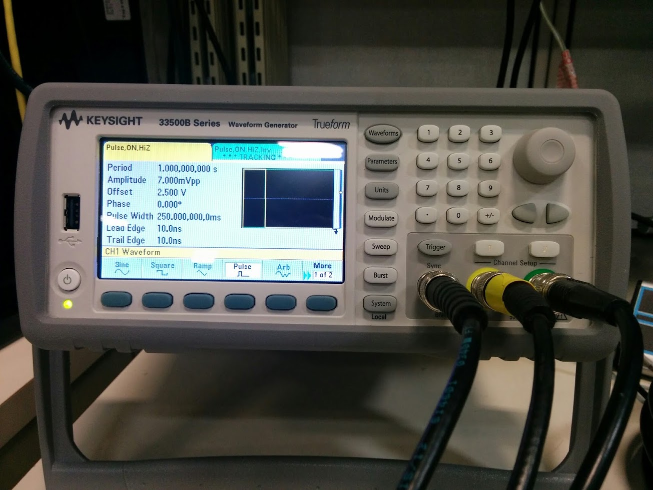
Test setup: waveform generator : 33500B series configured to differential signal output using two channels combined. Both devices connected in parallel. 

In pulse testing, both sigma delta have lost 50mS of data, which is also unexpected.

What am I missing here? Is this phenomenon anyway related with sigma delta group delay/ settling time issue ?

DATA: pdf

I found some of the legends are not proper. Please refer below: 

For all graphs Xaxis is time (mS)
Y axis: Counts
Blue color graphs are: SAR
Orange graphs are sigma delta.

Pulse testing different frequency_TI.pdf

  • Hi Niranjan,

    Thank you for your post!

    The group delay of the ADS1178 should be a constant 1.9ms as you calculated above. Just to be clear - you are comparing the output of the two ADCs? What are the FORMAT and MODE settings that you are using?

    Please share the data for 100Hz to 500Hz as well as the pulse-testing. 50ms sounds like an awfully long time - are you holding the device in /RESET at any point?

    I'll get back to you later today with more information.

    Best Regards,
  • ADS1178 is frame sync mode and SAR ADC is in SPI format. Yes I am comparing two ADCs SAR a legacy design we have and more or less the same amplifier parts. Only difference is SAR has 4 pole butterworth filter. But total group delays is in the around 100 microseconds from analog filters.

    In pulse testing, I lost the same amount of data on both SAR and sigma delta. You can see on slide 2. The input condition is shown in figure below

    period 1 Second
    pulse width 250 ms

    lead edge 10ns
    trail edge 10ns. Since I am missing on both, then there is something else.

    I will do 100hz to 500hz right now.

    Regarding /reset: In my knowledge No. I will double check. As far as I know, when it is triggered from micro, it should continue collecting data until it say stop. In the case of pulse, I took one second of data (only a portion is shown in slide 2) which is exactly one pulse (1 Second period).

  • Niranjan - I believe we overlooked a minor detail in your square wave plots. :)

    The plots for your faster input frequencies actually show the correct group delay - it may look like the edges of the delta-sigma output occur in-line with or slightly before  the edges of the SAR output, but in reality, the edges of the delta-sigma output actually correspond to an earlier SAR output edge. In other words, when the group delay in the output of the delta-sigma equals a multiple of the input signal period, the output will be 360 degrees out of phase with the input.

    At 500Hz, the 1.9ms of group delay accounts for almost 1 period of the input signal (i.e. the outputs are ~360 degrees out of phase). At 1kHz, this delay accounts for almost 2 periods (i.e. ~720 degrees).

    Let me know if this makes sense now.

  • I thought of this situation, that is why I decided to take multiple frequencies to test. But i just posted, to know, I really understood the group delay and settling time properly. Let me run a frequency sweep and different pulse to system and come back to you.

    Do you have any thoughts for losing 50ms on pulse test?

  • Thanks, Niranjan. I look forward to your results.

    Are you sure that all of the graphs show the correct time scale? 250ms should include 5,000 points at 20kSPS. Most of the slides appear to have the correct time scale with the exception of slide 6. Slide 6 appears to show a 2kHz square wave since the period is only 0.5ms. Also, I do not expect the waveform to be so heavily filtered at such a high data rate.

    If there was an issue with the ADS1178 resetting, I would expect the output to go low (negative supply) instead of returning to -3.5mV. Why are the leading edges of the output pulses aligned? I would expect slide 3 to show the same group delay for both edges, similar to slide 2, for example.

    Best Regards,

  • Hi Ryan,

    I apologize for delay in reply. 

    Thanks for the help. And you are right I am able to get the perfect delay as I calculated. I overlooked the relations 1.9ms and the frequencies I tested. More importantly, this discussion made strengthened my understanding . After your reply, I redesigned the test and able to get the accurate results. I am also able to overcome the data lose on our pulse testing too. I am attaching some results, of the test. 

    Thanks again for working with me.

    Phasetesting_TI.pdf

  • You're welcome, Niranjan. I'm glad to help. Please let us know if you have other questions.