This thread has been locked.

If you have a related question, please click the "Ask a related question" button in the top right corner. The newly created question will be automatically linked to this question.

I am puzzled about ADS1258

Other Parts Discussed in Thread: ADS1258

Hi,

I am puzzled about  the ADS1258 .

My ADS1258 works in differencial voltage  input mode with a +5V power supply for AVDD,and 0V for AVSS.

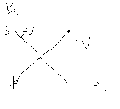
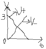
If i will suppply  ADCINP pin with a signal  ranging from 0V to +3V,and ADCINN pin  from +3V to 0V, neither of them  exceed the limitation(AVSS 100mV < Analog Inputs< AVDD + 100 mV),but the  differential voltage(ADCINP-ADCINN) ranges from -3V to 3V.So,i am wondering if the ADC is able to convert the bipolar signal into digital code correctly,and how to choose the reference voltage (VREFP,VREFN)?

  • Adam, 

    The full scale input of the ADC is +1.06Vref and Vref cannot exceed your power supply. So the maximum reference voltage you can use in your setup is 5V. If you have -3V on one channel and +3V on another channel, the differential voltage between the two signals is 6V. A 6V differential input will cause your ADC to clip once the input exceeds 1.06Vref and output data that will just read positive or negative full scale. I attached a document that highlights the data sheet specs you should focus on. From there you can setup your ADC appropriately. However, you are not going to be able to set up the ADC to convert differential voltages ranging from -3V to +3V. With a 5V supply and 5V reference, the max range you can achieve is abou -2.65 to +2.65V differentially. 

    Regards,

    Tony Calabria


    important specs.pdf
  • Hi,Tony.Thanks for your reply.

    I have understand part of your suggestion on choosing a suitable reference voltage. The datasheet tells me the fulll scale input voltage shouldn't exceed +/-1.06Vref,does it mean my differential input can be between -1.06Vref and +1.06Vref if using a +5V analog supply?

    I think i failed to discript my problem correctly.Actually ,I have  0V-3V signal on one channel,and 3V-0V on another,whithout minus voltage,so the differential voltage between the two signals is -3V to +3V,not 0V-6V,I'd like to show you the  curve

    At any time,the differential input is Vd=V+ - V-,from 3V to -3V.

    Regards,

    Adam


  • Adam, 

    Thank you for the clarification. Unfortunately, the link appears broken on the forum. Do you mind posting the picture again so I can see what you mean. 

    Looking at the Electrical Characteristics table, the absolute input voltage minimum is AVSS-100mV and the minimum the AVSS power supply can be is -2.6V shown on page 4. So, You cannot have a -3V differential input or you will be violating specs. 

    Regards,

    Tony Calabria

  • Tony,

    Thanks foir your reply.

    Firstly, I want to  check my conception of "absolute input voltage".Does it mean the input voltage respect to GND  on AINP or AINN pin?I always think so. 

    If it is,I would like to apply one signal ranging from 0V to 3V on AINP pin,and another signal ranging from 3V to 0V on AINN pin ,neither of  them  exceed the range of the absolute input voltage if the analog power supply is +5V.But the difference of the two pins would range from -3V (0V minus 3V) to +3V.(3V minus 0V).In ADS1258,the differential output(-3V to 3V) from MUX will be buffered to ADC input,is that OK?

    If you should fail to  see this link of picture again.I'd like to have you email  address and i'll sent it to you email box.Please look at the follwing  picture

    Regards,

    adam

  • Adam,

    Thank you for your picture and description. I did not fully understand what you were doing but I do now. You should not have any issue using the ADC in this configuration I have tested your setup on our EVM here to verify it works. I used a 5V power supply and a 5V reference and did not have any issues. 

    Regards,

    Tony Calabria

  • Tony,

    thank you a lot.

    I'll made a careful check.

    Regards,

    Adam