This thread has been locked.

If you have a related question, please click the "Ask a related question" button in the top right corner. The newly created question will be automatically linked to this question.

ADS1299 test signals

Other Parts Discussed in Thread: ADS1299

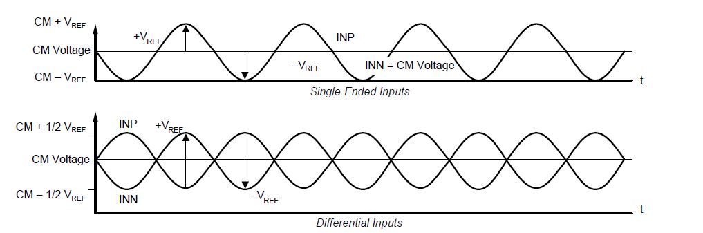
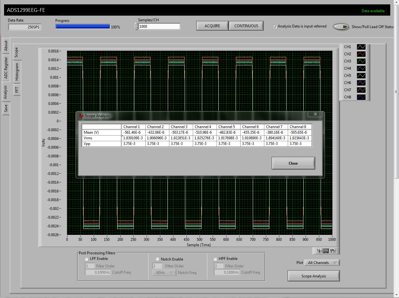
The test signal amplitude options are listed as +/- 1mv or +/- 2mV.  When configured for +/- 1mV the ADC produces a digital output of about 7000 counts peak to peak over time.  When configured for +/- 2mV the output is about 14000 peak to peak.  Are the output codes based on full scale of 4.5V VRef or 9V of -VRef to +VRef?

  • Hi Paul,

    Full-scale refers to the value of Vref, so 4.5V in this case. The weight of one code (i.e. the LSB size) is equal to (2*Vref/Gain / 2^24). In other words, the ADS1299 uses 2^24 codes to represent the span of differential input-referred voltages that can be converted (from -4.5V/Gain to +4.5V/Gain).

    Best Regards,
  • Ryan,

    Based on the weight of one code (i.e. the LSB size) equal to (2*Vref/Gain / 2^24) and codes of 7000 and 14000 for the two test signal amplitudes should the spec for the test signals be +/- 2mV and +/- 4 mv? 

  • If you are using a Gain = 2, then yes. The input-referred amplitude of the test signal should always be 1mV for CONFIG2[2] = 0 and 2mV CONFIG[2] = 1. I believe the CONFIG2 page of the datasheet contains a typo and the equation should read ((VREFP – VREFN) / 4.5) mV.

    Best Regards,
  • Ryan,

    The gain is 1.

    On page 3 of the data sheet the following is listed under Analog Inputs
    "Full-scale differential input voltage (AINP – AINN) ±VREF / gain"
    Does this imply that with VREF = 4.5 V and a gain of 1 the input range is 9V from -4.5V to + 4.5V ?
  • Yes, the differential input voltage range is from -4.5V to +4.5V with PGA gain = 1. Please refer to the figure below:

    Would you mind sharing your raw data and register settings? Also, are you using our ADS1299EVM or your own hardware?

    Best Regards,

  • Ryan,


    Here is a raw data dump for about one second of time in the attached file.  Data was read in off the 1299.  I added the 0x00 after each 24 bits to make it easier to read.


    The range shown is about ff ee 70 to 00 09 af, so that should be to –4496 to +2497 = 6993.

    Based on 9V range I calculate 3.75mVp-p in the +/-1mV test configuration.

    Test signal raw data dump.docx

  • Hi Paul,

    Thanks for sharing the data. I also took some data on the bench using the ADS1299EVM and saw the same results that you observed. It looks like the typo actually exists on page 4 of the datasheet in the Electrical Characteristics table. The typical amplitudes are not +/-1mV or +/-2mV. This must be a copy/paste error from devices that use a typical reference voltage of 2.4 V.

    Instead, the test signal amplitude should read +/-1.875mV or +/-3.75mV. The equations on page 41 in the CONFIG2 register are correct. The User Guide section 5.3.1 (Figure 20) will also have to be updated.

    Here is a screen capture of my data (Gain = 1, CONFIG2[2] = 0):


    I'm sorry it took this long to realize the error.

    Best Regards,