This thread has been locked.

If you have a related question, please click the "Ask a related question" button in the top right corner. The newly created question will be automatically linked to this question.

Sometimes, ADS1296 outputs 0 values for all channels

Other Parts Discussed in Thread: ADS1296

Hello,

I have a new issue with the ADS1296: I toggle between conversion + read continuous and stop conversion + stop continuous mode and sometimes I have only 0 for all channels data???

I toggle the commands every 5-10 seconds.

Here is my code:

/*********************************************************************************************************
* ADS129x_RDATAC : enable read continuous mode (this mode is the default reset mode)																	                 *
**********************************************************************************************************/
void ADS129x_RDATAC_cmd(void)
{
    Acq_state = ACQ_CONTINUOUS;
    ADS_CS_ON;
    spi_send_byte_spi3(0x10);
    ADS_CS_OFF;
    Enable_ADS129x_DRDY_Interrupt();
    Timers_WaitA0(TIMER_A0_1, WAIT_10MS);
    ADS_START_ON;
    Timers_WaitA0(TIMER_A0_1, WAIT_10MS);
}


/*********************************************************************************************************
* ADS129x_SDATAC_cmd : stop continuous mode (this mode is the default reset mode)																	                 *
**********************************************************************************************************/
void ADS129x_SDATAC_cmd(void)
{
    Acq_state = ACQ_STOP;
    ADS_START_OFF;
    Timers_WaitA0(TIMER_A0_1, WAIT_10MS);
    ADS_CS_ON;
    spi_send_byte_spi3(0x11);
    ADS_CS_OFF;
    Timers_WaitA0(TIMER_A0_1, WAIT_10MS);
    Disable_ADS129x_DRDY_Interrupt();
}

The SPI clk frequency is 1MHz.

Please find here the scope images:

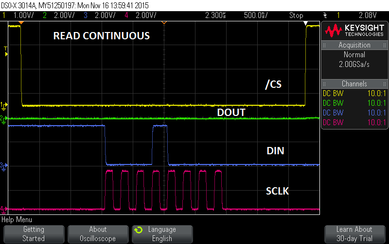
Is there any delay needed between SPI command and START pin?  I tried 50µsec and 10msec but the result is always the same: sometimes all channels ouputs 0 ?????

Best regards

Mich

  • Hi Mich,

    How long is START high before you read data? When START is taken high, /DRDY will indicate when new data is available after the digital filter settles. If you are trying to read data before /DRDY (or while START is still low), then you may see all 0s on DOUT.

    Can you add START and /DRDY to the above images?

    Regards,
  • Hi Ryan,
    I will add image tomorrow.
    But I can explain it:
    - The Enable Read Continuous command is sent.
    - I authorize interrupt in the MSP340
    - Wait 1msec (the same for wait 10msec previously tested)
    - The START pin is set high and stays high during all the time needed (all the test if data ok: 10 monutes, 1 hour ....)
    - As soon as an interrupt is received from the /DRDY the MSP430 reads the data
    - the Data Rate is 250 samples per seconds
    - If the issue occurs, all data are at 0 all the time, It could last 1 hour or more if I do not change anything. The above image is a zoom but it occurs at each /DRDY <-> read cycles

    If this problem occurs (could be 10% of the case) I stop the device (START pin at low + Stop Continuous command) then I restart the conversion (Enable Read Continuous command + START pin at high). Then it could solve the issue.

    Could this explain the issue?
    What am I wrong?
    Does anyone meet the same issue?
    I have another issue during power up which occurs sometimes too:
    e2e.ti.com/.../469534

    Is the ADS1296 new or is it a highrunner component?

    Best regards
    Michel
  • Hi Ryan,


    Please find here the requested image:

    Do you have any suggestion?

    Best regards

    Michel

  • Obviously the issue is around the Enable Read Data Continuous command.
    I bypass the issue by not using the continuous mode at all and I use the Read Data command at each interrrupt.
    Is there any specific timing betweeen the START pin state modification and the Continuous mode command?
    I did not see anything in the datasheet and there is no errasheet for the component. Do you have more information?
  • Hi Mich,

    Thanks for the updates.

    No, there is no relation between toggling the START pin and sending other SPI commands. As long as START is high, the ADC modulator is converting. RDATAC simply loads the data automatically into the output shift register before every /DRDY interrupt.

    Upon power-up or a /RESET, the ADS1296 default is Read Data Continuous - you do not need to send the RDATAC command to use this mode.

    Actually, that may be the problem! The device is in RDATAC mode by default. Before you send ANY other commands, you must first send SDATAC. If you send another RDATAC command while you are already in RDATAC mode, you may put the device in an unknown state...

    Please do not issue RDATAC upon start-up and see if data comes out correctly.

  • Hi Ryan,

    We are in the debug state so the product is as follow:
    A PC IHM, a bluetooth link between the PC and the PCBA. PCBA: MPS430 + ADS1296 + Bluetooth + µSD card
    The PC IHM can send configuration and read data from the MSP430 which links to the ADS1296.
    At Power up the Continuous mode is stopped to permit us to configure the ADS1296 from the IHM.
    The IHM displays (and optionnally save in a file) realtime data. We use 250 data rate actually.

    So by IHM we can have these sequences:
    - Configuration and read back registers => OK
    - Start acquisition and display data => OK
    - stop acquisition => OK
    - Start acquisition and display data => OK
    - stop acquisition => OK
    - Start acquisition and display data => all zeros => oscilloscope shows that the DRDY has falling edges, so the MSP430 trigs a read sequence but DOUT is always 0 ????? I imagined that the previous RDATAC is not passed but may be it is something else....
    - stop acquisition => OK
    - Start acquisition and display data => OK
    - stop acquisition => OK
    - Start acquisition and display data => OK

    Details concerning Start and Stop command at the MSP430-ADS1296 level are described at the beginning of the post.

    DOUT at 0 concerns around 10% of the acquistion sequence. When it occurs, it lasts up to the next Stop/Start sequence. It occurs randomly.
    We tested many PCBA so it is not a solder issue.

    I will send the schematic to Brian Pisani as soon as he will give me his email address.

    Best regards
    Michel