This thread has been locked.

If you have a related question, please click the "Ask a related question" button in the top right corner. The newly created question will be automatically linked to this question.

AFE5801 with TSW1400EVM

Other Parts Discussed in Thread: AFE5801, AFE5801EVM

I recently purchased the AFE5801 EVM and TSW1400.  Right now I am just trying to verify that the signals go through and are captured by TSW1400.  Somehoe i cannot things to work. A few details on my setup:

1. I am using the AFE in internal 40MHz CLK mode. My understanding is that the default position of P4 jumper would suffice, so I am not doing anything to supply the external clock.

2. For some reason, the tab on AFE GUI (TI ADC SPI interface) shows "Init for TSW 1250" instead of TSW 1400. Is that okay?

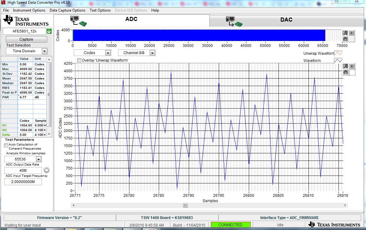
3. Input to channel 8 of ADC is 2 MHz Sin wave as described in the user manual. When I select FFT mode on HSDC Pro (TSW's GUI), I can only see noise floor, even time domain data doesn't make any sense. In fact even if i remove the input signal, i can just see noise floor. Somehow it seems that signal is not passing through AFE. AFE gain is set to 30dB, i tried to change it but no help.

I think I am missing something basic. Please advise. 

-Gaurav

  • Gaurav,

    Can you please confirm that you received the adapter card with the AFE5801 EVM?  This card goes between the AFE EVM and the TSW1400.  Sometimes this is missing in the kit. The "init for TSW1250"  button is okay.  Can you please enable the ramp test pattern using the "Pattern_Mode"? The internal clock should be okay.

    Thanks,

    Chuck Smyth

  • Hi,

    Yes, I received a connector card.

    I enabled the ramp pattern. It looks like a 'noisy ramp' at best. I have attached a screenshot of ramp pattern for your review. Same noisy behavior with external sine wave input. The FFT sometimes shows a tiny spur at 2M (input frequency), but the noise floor is too high to be definitive. Toggle pattern seems fine.

    thanks,

    Gaurav

  • Hello Gaurav,

    Thanks for using TI AFE5801 device.

    We are verifying your questions and we will also test the same conditions as you mentioned in our lab.

    We will let you know very soon.

    Thank you!

    Best regards,

    Chen

  • Thank you. I wanted to give a few more details in case it helps you debug:
    When I give an external input to AFE (2MHz clean CLK), using the 40MHz internal clock on board, I notice that the ADC output codes are usually saturated (hit 4096) even is the input signal is very small (200mV) AND the gain is set to -6dB. This is strange I think. Also, even on channels that do not have any input, the ADC output codes swing a lot (1000 codes - almost like some noise is there). In general the noise floor after taking FFT is very high (around -40dB), as opposed to -100dB as is shown in TI's documents.
    I'll wait for your reply.
  • Send E2E AFE5801+TSW1400 reply to customer Gaurav.pdfHello Gaurav,

    How are you?

    Thanks for using our AFE5801 EVM and TSW1400 EVM.

    Yes, we re-tested all the test conditions which you just shown.

    We can see the same test results. They are due to the AFE5801 data sheet changing

    on some register settings which are not used any more.

    Please take a look at the attached (more detail information) file.

    Again, thank you for using TI AFE5801 device.

    Have a nice day!

    Best regards,

    Chen

  • Hi,

    Thanks for the debug, this fixes the ramp issue !! Also, I see better waveforms with sinusoidal inputs. Great!

    Now, I still see some issue with the gain / input swing. let me explain:

    When we input a 1V pk-pk sinusoid, and use a 0dB gain , I expect that the signal uses full range of ADC, so the codes plotted by TSW1400 should look like a sinusoid between 0 and 4098 [or something like that]. But I see a very small movement in code around mid code of 2048. In fact when I set the gain to 30dB, even with a 1V pk-pk input swing, I get just +/- 10 codes amplitude sinusoid in the plot. This should have just saturated the ADC input, but still the signal is too small.

    I am use offset binary format for AF5801.

    Please advise how to utilize the full range of ADC,

    thanks again for the 'LSB first' debug.

    Gaurav

  • Hello Gaurav,

    How are you?

    Here is the detailed explanation of how AFE5801 and TSW1400 settings

    of the gain testing.

    Please take a look at the attached file.

    If you don't see the LED turned on, please try to turn off the EVM power supply

    and turn off its GUI and then re-turn them back on again.

    Thanks and best regards,

    ChenTest AFE5801 and Confirm Range (0~4095) is ADC 2Vpp limit to Customer Gaurav (sent to).pdf

  • Hello Chen,

    Thanks for the detailed description. I validated that the setup is as what you describe in the above pdf. I am giving a 1V pk-pk input a/c coupled into the SMA connector. I also probed the PINs CH1N & CH1P, verified that the swing is 500mV and the common mode is 1.6V roughly. But somehow, with 0dB gain settings, I get a very small output (as captured with TSW1400 EVM) - just about 2-4 codes of swing centered on mid code of 2048. With 30dB Gain, I can se 10-20 codes of swing, but no where near full swing.

    Now, given that the internal ramp pattern goes from 0 - 4096 even in my setup, is it possible that the Gain settings or its circuit may be faulty. Else, please suggest some other test to debug. Should we replace the board?

    thanks for your help,

    Gaurav

  • Hello Gaurav,

    How are you?

    Thanks for replying your test conditions.

    Sounds like it could be due to the register setting issues.

    When you set up the registers on the AFE5801 GUI, when you are using decimal then you can see

    the icon showing "d" (that means decimal) and when you see the icon showing "x" (that means Hex).

    Therefore you need to enter the right type of number for it.

    Also on TSW1400 GUI, please check all the channels (totally 8 channels)

    and see if the signal appears on the wrong channel screen or not?Test AFE5801 and Confirm Range (0~4095) is ADC 2Vpp limit to Customer Gaurav (2 tests New).pdf

    Here are more explanations and please try the same methods

    (please see the attached file).

    Also we tested two Gains (One is Gain=0dB and the other one is Gain=6dB)

    and both are working as you can see (using the same 1Vpp input sine wave signal).

    At Gain=0dB, we can receive -6dBFS (Half-Scale) at the ADC output

    At Gain=6dB, we can receive 0dBFS (Full-Scale) at the ADC output

    Thank you!

    Have a nice day!

    Best regards,

    Chen

  • Hi,

    I verified that I am using the correct number format (hex), I entered the values per your instructions. It makes not difference.

    I also checked all channels, signal appears on the right channel but is very small. For example, the figure below is for a 30dB gain!

    Any other suggestions? Is it likely that this is a faulty part & and I should change it?

    Please advise.

    thanks,

    Gaurav

  • Hello Gaurav,

    How are you?
    It looks like it is pretty strange condition.
    First of all, could you please turn off all the power supplies for AFE5801EVM and TSW1400EVM and also disconnect both USBs (one used for AFE5801EVM and
    the other one used for TSW1400EVM)?
    Also, please quite both AFE5801GUI and TSW1400GUI from your PC as well.
    (Note: in our lab we are using Windows 7)
    Then please re-turn on your EVM setups and their power supplies (+5V, GND) and Power Adapter.
    After that, please re-start both GUIs (AFE5801GUI and TSW1400GUI).
    Then after you re-run AFE5801 device with TSW1400 capture board,
    could you please send me the plot from your TSW1400 GUI?
    here is my email chen.kung@ti.com if this is convenient for you.

    Thank you!
    Have a very nice weekend!

    Best regards,
    Chen
  • Hi,
    Did the power downs, restarted. Same behavior. Just sent you the plots from TSW GUI.
    thanks,
    Gaurav
  • Hello Gaurav,

    Thank you very much for replying to us.
    I will continue to show to and discuss with Chuck.
    We will reply to you very soon.

    Have a nice weekend!

    Best regards,
    Chen
  • Hi Gaurav,

    I saw the images in the email. The FFT and time domain signal look normal for a channel with only noise only perhaps a neighboring channel to the active channel. Obviously we can see the hint of a 2MHz signal. Can you please verify that you have scrolled through all of the channels in HSDCPro to make sure it is not showing up on another channel. It seems that the ADC is working and the VCA is working to some extent, but there is no gain. The TSW1400 seems ok. Can you please specifiy your 2MHz input power.

    Chuck
  • Hi Chuck,

    I confirm that I have checked on all other channels, and there is no tone there, just noise floor. Even without any gain, I'd expect a bigger signal, so I am not what is going on.

    The 2MHz signal is 1V peak-to-peak. Also, as I mentioned earlier I've verified the common mode and peak to peak all the way upto pins CH1P & CH1N at the input of the chip - they match your pdf. Something inside the chip is not quite right.

    thanks,

    Gaurav