This thread has been locked.

If you have a related question, please click the "Ask a related question" button in the top right corner. The newly created question will be automatically linked to this question.

AFE4404 Heart rate calulation

Other Parts Discussed in Thread: AFE4404

Hello All,

I have purchased AFE4404 IC as well as AFE4404  EVM,

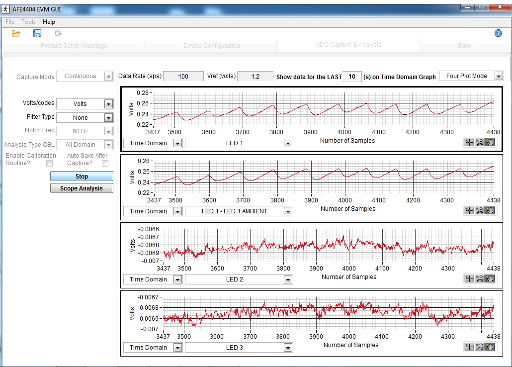
I have configured EVM GUI and got sawtooth wave forms so taken those registers settings and went ahed after applying so many other ways I am not able to get heart rate.

There is not a single response from TI support side, even I found no document mentioning about the heart rate , I have posted even some of the queries related to that but got deleted and in initial conversation I got some of the links 

- e2e.ti.com/.../1653596

- e2e.ti.com/.../369445 (see #18 question)

- e2e.ti.com/.../462275

I tried to follow them even but still I am unable to get heart rate so I request you to help me to get heart rate.

Or is there any one who has/had worked upon this IC to calculate heart rate ?

Did I chose the wrong IC to calculate Heart rate ?

Any help on this would be greatly appreciated.

Thanks & Regards,

Rutvij.

  • Hello Rutvij,

    We understand your concerns.
    Can you forward the links of the posts you had posted earlier with your register settings and output data as well as waveform?
    We do not delete the posts. But if your posts have been deleted, can you please repost your queries again?

    The latest version of the AFE4404 EVM firmware source code located at www.ti.com/.../afe4404evm includes the non-motion compensated heart rate algorithm. The code is provided AS IS.
    Here is the link for your reference: www.ti.com/.../slac718
  • Hello Praveen Aroul,

    I have used the same code before to start work with but unfortunately it didn't work.

    I have commented SPO2  calculation part but Heart rate calculation is used as it is.

    I have used may configuration then after for register configurations.

    AFE4404.h

    /*
     * Calibration_AFE4404.c
     *
     * Provides AFE4404 calibration API
     *
     * Copyright (C) 2015 Texas Instruments Incorporated - http://www.ti.com/ 
     * ALL RIGHTS RESERVED  
     *
    */
    
    #include "AFE4404.h"
    #include "Calibration_AFE4404.h"
    
    /*******************************************************************************/
    /*	        Global Variables										       	   */
    /*******************************************************************************/
    /* Constants Definitions */
    const unsigned long ADC_FULL_SCALE = 0x200000;   				// ADC Full scale
    const unsigned long ADC_TEN_PERCENT_FS = 209715; 				// 10% of ADC Full scale
    const unsigned long ADC_ONE_PERCENT_FS = 20971; 				// 1% of ADC Full scale
    
    const unsigned int TFREEZE = 2;   								// Time in seconds between two periodic calibrations
    const unsigned int TIMEWAIT = 2; 								// Duration (Number of PRFs) to wait after a configuration change
    
    const unsigned int BLOCK_SIZE_BITS = 3; 						// Samples Window size = 2^BLOCK_SIZE_BITS for measuring DC value
    const unsigned int BLOCK_SIZE = 8; 							// Number of samples required to calculate the DC value
    
    const unsigned int LED1_reg_shift = 0;							// LED1 current reg - LSB bit position
    const unsigned int LED2_reg_shift = 6;							// LED2 current reg - LSB bit position
    const unsigned int LED3_reg_shift = 12;							// LED3 current reg - LSB bit position
    
    const unsigned long LED1_mask = 0x00003F;						// LED1 current - mask bits
    const unsigned long LED2_mask = 0x000FC0;						// LED2 current - mask bits
    const unsigned long LED3_mask = 0x03F000;						// LED3 current - mask bits
    
    const unsigned int AMB_reg_shift_led1 = 5;						// Shift position for OFFDAC - LED1
    const unsigned int AMB_reg_shift_amb1 = 10;						// Shift position for OFFDAC - AMB1
    const unsigned int AMB_reg_shift_led2 = 15;						// Shift position for OFFDAC - LED2
    const unsigned int AMB_reg_shift_amb2 = 0;						// Shift position for OFFDAC - LED3 / AMB2
    
    const unsigned long AMB1_mask = 0x007FE0; 						// Mask for OFFDAC for LED1 and AMB1
    const unsigned long AMB2_mask = 0x0FFC00; 						// Mask for OFFDAC for LED2 and AMB1
    const unsigned long AMB3_mask = 0x007C1F; 						// Mask for OFFDAC for LED3 and AMB1
    const unsigned long AMB23_mask = 0x0FFC1F;						// Mask for OFFDAC for LED2, LED3 and AMB1
    const unsigned long AMB123_mask = 0xFFFFF;						// Mask for OFFDAC for LED1, LED2, LED3 and AMB1
    
    const unsigned long AMB1_mask_LED = 0x0003E0;					// Mask for OFFDAC for LED1 only (no AMB1)
    const unsigned long AMB2_mask_LED = 0x0F8000;					// Mask for OFFDAC for LED2 only (no AMB1)
    const unsigned long AMB3_mask_LED = 0x00001F;					// Mask for OFFDAC for LED3 only (no AMB1)
    const unsigned long AMB23_mask_LED = 0x0F801F;					// Mask for OFFDAC for LED2 and LED3 only (no AMB1)
    const unsigned long AMB123_mask_LED = 0x0F83FF;					// Mask for OFFDAC for LED1, LED2 and LED3 only (no AMB1)
    
    const unsigned int ILED_CURR_MIN_code = 2; 							// LED min current reqd. for application - 3.2 mA assuming 100mA range (This is default value)
    const unsigned int ILED_CURR_MAX_code = 55; 							// LED max current reqd. for application - 88 mA assuming 100mA range (This is default value)
    
    const short unsigned int LOW_THR_PERCENT = 10;       			// Low Threshold Percent
    const short unsigned int HIGH_THR_PERCENT = 90;      			// High Threshold percent
    const short unsigned int HYS_PERCENT = 3;            			// Hysteresis percent
    const short int TARGET_THR_PERCENT = 50;    					// Target Threshold percent
    
    long TARGET_THR; 												// Target threshold for Gain Calibration
    long LOW_THR_HYS_LOW; 											// Low threshold for gain calibration in periodic mode
    long LOW_THR_HYS_LOW_USER;
    long LOW_THR_HYS_LOW_LED2;
    long LOW_THR_HYS_HIGH; 											// Low threshold for gain calibration
    long HIGH_THR_HYS_LOW; 											// High threshold for gain calibration
    long HIGH_THR_HYS_HIGH; 										// High threshold for gain calibration in periodic mode
    
    unsigned long ADC_CODE_AMB_DAC_MIN = 43690;			 			// ADC output for 0.25uA pleth current with Rf = 50K
    unsigned long ADC_CODE_AMB_DAC_STEP = 65000;		 			// Step size at the ADC output for an increase of 0.5uA pleth current with Rf = 50K ==> 0.5uA * 100K in codes
    unsigned long ADC_CODE_AMB_DAC_STEP_IDEAL = 87381;
    
    extern volatile int g_OneSecondFlag; 							// Flag to indicate the HRM has generated an SNR value (This flag is set in the ISR for ADC ready interrupt after every second)
    unsigned int Ambient_DAC_enabled = 0; 							// Indicates whether the AMB_DAC cancellation is used or not
    
    CALIBRATION_STATES AmbientDACcalibration_state = sInit;
    CALIBRATION_STATES Gaincalibration_state = sInit;
    CALIBRATION_MODES calibration_mode = sAmbientDAC;
    PERIODIC_MODES PeriodicCalibration_state = sFreeze_periodic;
    OFFSETDAC_CALIB_STATES OffsetDAC_code_Est_state = sOffsetDACInit;
    CALIB_ENABLE Calibration_en;
    FLAGS flag;
    SYSTEM_PARAMS system;
    SIGNAL_PARAMS signal;
    
    int Calibration = 1;  						// Indicates whether calibration is ON
    unsigned int Periodic_started = 0; 			// Indicates whether periodic calibration has started or not
    int Cf_array[8] = { 250, 250, 250, 250, 250, 250, 250, 250 };
    unsigned long AFE44xx_Current_Register_Settings[5] = { 0, 0, 0, 0, 0 }; // Array that holds the latest AFE register settings
    // For any AFE register change - update the appropriate element
    // in the array corresponding to the register
    // 0 for register 0x22 - LED current
    // 3 for register 0x3A - Amb gain
    unsigned int Enable_sep_gain = 1;
    unsigned int DC_can = 0;
    int LED_pulse_width = 0;
    // Selection of either LED1 or LED2 or LED3 in MODE1 (HRM only mode)
    char LED_Sel = 1;
    RF_VALUES RFValue_Init_GainCal = s2M; 							// Initial Rf for Gain calibration (if ambient dac is not enabled)
    unsigned int periodic_cal_req = 0;
    unsigned long Ipleth = 1875;
    unsigned int LED_DC_can = 6;
    
    // Use this for 50mA range
    // int Ipleth_array[5] = { 1250, 1875, 2500, 3125, 3750 }; // codes for 1uA, 1.5uA ... 3uA expressed as 1000nA/0.8mA -- unit code is 0.8mA
    // Use this for 100mA range
    int Ipleth_array[5] = { 625, 938, 1250, 1563, 1875 }; // codes for 1uA, 1.5uA ... 3uA expressed as 1000nA/1.6mA -- unit code is 1.6mA
    long CTR = 0;
    
    long meas_DC_arr[8];
    
    
    /*********************************************************************
    * @fn      		setRfValue
    *
    * @brief		takes in Rf in RF_VALUES type and update the AFE44xx_Current_Register_Settings[1] accordingly
    *
    * @param   		RF_VALUES
    *
    * @return  		void
    *
    *********************************************************************/
    void setRfValue(RF_VALUES rfvalue) 
    {
      switch (rfvalue) 
      {
        case (s2M):	// Set TIA gain to 2 MOhm.
        AFE44xx_Current_Register_Settings[2] = (AFE44xx_Current_Register_Settings[2] & ~(0x00007)) | (0x00007);
    	system.Cf = Cf_array[0];
        break;
        
        case (s1M): // Set TIA gain to 1 MOhm.
        AFE44xx_Current_Register_Settings[2] = (AFE44xx_Current_Register_Settings[2] & ~(0x00007)) | (0x00006);
    	system.Cf = Cf_array[1];
        break;
        
        case (s500K): // Set TIA gain to 500 kOhm.
        AFE44xx_Current_Register_Settings[2] = (AFE44xx_Current_Register_Settings[2] & ~(0x00007)) | (0x00000);
    	system.Cf = Cf_array[2];
        break;
        
        case (s250K): // Set TIA gain to 250 kOhm.
        AFE44xx_Current_Register_Settings[2] = (AFE44xx_Current_Register_Settings[2] & ~(0x00007)) | (0x00001);
        system.Cf = Cf_array[3];
    	break;
        
        case (s100K): // Set TIA gain to 100 kOhm.
        AFE44xx_Current_Register_Settings[2] = (AFE44xx_Current_Register_Settings[2] & ~(0x00007)) | (0x00002);
        system.Cf = Cf_array[4];
    	break;
        
        case (s50K): // Set TIA gain to 50 kOhm.
        AFE44xx_Current_Register_Settings[2] = (AFE44xx_Current_Register_Settings[2] & ~(0x00007)) | (0x00003);
        system.Cf = Cf_array[5];
    	break;
        
        case (s25K): // Set TIA gain to 25 kOhm.
        AFE44xx_Current_Register_Settings[2] = (AFE44xx_Current_Register_Settings[2] & ~(0x00007)) | (0x00004);
    	system.Cf = Cf_array[6];
        break;
        
        case (s10K): // Set TIA gain to 10 kOhm.
        AFE44xx_Current_Register_Settings[2] = (AFE44xx_Current_Register_Settings[2] & ~(0x00007)) | (0x00005);
    	system.Cf = Cf_array[7];
        break;
        
        default: // Set Default TIA gain to 10 kOhm.
        AFE44xx_Current_Register_Settings[2] = (AFE44xx_Current_Register_Settings[2] & ~(0x00007)) | (0x00005);
    	system.Cf = Cf_array[7];
      }
    }
    
    /*********************************************************************
    * @fn      		setCfValue
    *
    * @brief		takes in Cf in int type and update the AFE44xx_Current_Register_Settings[2] accordingly
    *
    * @param   		int
    *
    * @return  		void
    *
    *********************************************************************/
    void setCfValue(int Cfvalue) 
    {
      switch (Cfvalue) 
      {
        case (250):	// Set Cf = 25 pF
        AFE44xx_Current_Register_Settings[2] = (AFE44xx_Current_Register_Settings[2] & ~(0x00038)) | (0x00030);
        break;
        
        case (200):	// Set Cf = 20 pF
        AFE44xx_Current_Register_Settings[2] = (AFE44xx_Current_Register_Settings[2] & ~(0x00038)) | (0x00020);
        break;
        
        case (100):	// Set Cf = 10 pF
        AFE44xx_Current_Register_Settings[2] = (AFE44xx_Current_Register_Settings[2] & ~(0x00038)) | (0x00010);
        break;
        
        case (50): // Set Cf = 5 pF
        AFE44xx_Current_Register_Settings[2] = (AFE44xx_Current_Register_Settings[2] & ~(0x00038)) | (0x00000);
        break;
        
        case (25): // Set Cf = 2.5 pF
        AFE44xx_Current_Register_Settings[2] = (AFE44xx_Current_Register_Settings[2] & ~(0x00038)) | (0x00008);
        break;
    	
        default: // Set Cf = 2.5 pF
        AFE44xx_Current_Register_Settings[2] = (AFE44xx_Current_Register_Settings[2] & ~(0x00038)) | (0x00008);
      }
    }
    
    /*********************************************************************
    * @fn      		initCalibrationRoutine
    *
    * @brief		Initializes Calibration routine variables
    *
    * @param   		void
    *
    * @return  		void
    *
    *********************************************************************/
    void initCalibrationRoutine(void) 
    {
    	unsigned int Calibration_enabled = 0;
    	unsigned int Ipleth_num;
      
    	Calibration = 1;
    	Calibration_en.AMB = 1; // Check for calibration modes
    	Calibration_en.GAIN = 1;
    	Calibration_en.PERIODIC = 1;
      
    	// Selection of either LED1 or LED2 or LED3 in MODE1 (HRM only mode)
    	LED_Sel = 1;
      
    	Ipleth_num = 4;
    	Ipleth = Ipleth_array[Ipleth_num];
    	LED_DC_can = Ipleth_num + 2; // When Iplethnum = 0, (1uA) corresponds to reg settings of 2 (reason for why +2)
      
    	LED_pulse_width = 25;  //LED pulse width in us
    	if (LED_pulse_width >= 500) 
    	{
    		Cf_array[0] = 250;
    	} 
    	else if (LED_pulse_width >= 400) 
    	{
    		Cf_array[0] = 200;
    	} 
    	else if (LED_pulse_width >= 200) 
    	{
    		Cf_array[0] = 100;
    		Cf_array[1] = 200;
    	} 
    	else if (LED_pulse_width >= 100) 
    	{
    		Cf_array[0] = 50;
    		Cf_array[1] = 100;
    		Cf_array[2] = 200;
    	} 
    	else if (LED_pulse_width >= 50) 
    	{
    		Cf_array[0] = 25;
    		Cf_array[1] = 50;
    		Cf_array[2] = 100;
    		Cf_array[3] = 200;
    	} 
    	else if (LED_pulse_width >= 25) 
    	{
    		Cf_array[0] = 25;
    		Cf_array[1] = 25;
    		Cf_array[2] = 50;
    		Cf_array[3] = 100;
    		Cf_array[4] = 200;
    	} 
    	else 
    	{
    		Cf_array[0] = 25;
    		Cf_array[1] = 25;
    		Cf_array[2] = 25;
    		Cf_array[3] = 25;
    		Cf_array[4] = 25;
    		Cf_array[5] = 25;
    		Cf_array[6] = 25;
    		Cf_array[7] = 25;
    	}
      
    	calibration_mode = sAmbientDAC; //calibration mode is set to Ambient Cancellation
    	AmbientDACcalibration_state = sInit;
    	Gaincalibration_state = sInit;
    	PeriodicCalibration_state = sFreeze_periodic;
      
    	Periodic_started = 0;
    	flag.GainCalib = 0;							//flags are initialized to zero
    	flag.AmbCancel = 0;
      
    	system.ILED = ILED_CURR_MIN_code;
    	system.ILED2 = ILED_CURR_MIN_code;
    	system.AMB_DAC_LED = 0;
    	system.AMB_DAC_SIGN_LED = 1;          // sign: 1 - positive and 0 - negative
    	system.AMB_DAC_AMB = 0;
    	system.AMB_DAC_SIGN_AMB = 1;
    	signal.DC = 0;
    	system.RF = s50K;            //sets the initial system and signal parameters
    	system.Cf = 25;
      
    	Calibration_enabled = Calibration_en.AMB + Calibration_en.GAIN + Calibration_en.PERIODIC;
      
    	if (Calibration_enabled != 0) 
    	{
    		AFE44xx_Current_Register_Settings[2] = 0;
        //AFE44xx_Current_Register_Settings[1] = 0;
    		// Mods to support selection of either LED1 or LED2 or LED3 in MODE1 (HRM only mode) - 03/24/2015
    		if (LED_Sel == 2) 
    		{
    			AFE44xx_Current_Register_Settings[0] = (AFE44xx_Current_Register_Settings[0] & (~LED2_mask));	
    			AFE44xx_Current_Register_Settings[3] = (AFE44xx_Current_Register_Settings[3] & (~AMB2_mask));
    		}
    		else if (LED_Sel == 3) 
    		{
    			AFE44xx_Current_Register_Settings[0] = (AFE44xx_Current_Register_Settings[0] & (~LED3_mask));	
    			AFE44xx_Current_Register_Settings[3] = (AFE44xx_Current_Register_Settings[3] & (~AMB3_mask));
    		}
    		else //Default is LED1
    		{
    			AFE44xx_Current_Register_Settings[0] = (AFE44xx_Current_Register_Settings[0] & (~LED1_mask));	
    			AFE44xx_Current_Register_Settings[3] = (AFE44xx_Current_Register_Settings[3] & (~AMB1_mask));
    		}
    
    		AFE4404_Reg_Write(AFE_CONTROL0, 0x00000000); // write mode
    		AFE4404_Reg_Write(AFE_LEDCNTRL, AFE44xx_Current_Register_Settings[0]);    //0x20
        //AFE4404_Reg_Write(AFE_TIAGAIN, AFE44xx_Current_Register_Settings[1]);
    		AFE4404_Reg_Write(AFE_TIAAMBGAIN, AFE44xx_Current_Register_Settings[2]);
    		AFE4404_Reg_Write(AFE_DAC_SETTING_REG, AFE44xx_Current_Register_Settings[3]);
    		AFE4404_Reg_Write(AFE_CONTROL0, 0x00000001); // read mode
    	}
      
    	//Enable_sep_gain = (AFE44xx_Current_Register_Settings[1] & 0x8000)>>15;
    	LOW_THR_HYS_LOW = ((LOW_THR_PERCENT - HYS_PERCENT) * ADC_FULL_SCALE) / 100;
    	LOW_THR_HYS_LOW_USER = LOW_THR_HYS_LOW;
    	LOW_THR_HYS_LOW_LED2 = LOW_THR_HYS_LOW;
    	LOW_THR_HYS_HIGH = ((LOW_THR_PERCENT + HYS_PERCENT) * ADC_FULL_SCALE) / 100;
    	HIGH_THR_HYS_LOW = ((HIGH_THR_PERCENT - HYS_PERCENT) * ADC_FULL_SCALE) / 100;
    	HIGH_THR_HYS_HIGH = ((HIGH_THR_PERCENT + HYS_PERCENT) * ADC_FULL_SCALE) / 100;
    	TARGET_THR = ((TARGET_THR_PERCENT * ADC_FULL_SCALE) / 100);
    	DC_can = 0;
    }
    
    /*********************************************************************
    * @fn      		AmbientCancellation
    *
    * @brief		Looks at the Ambient values and cancels it off using the AMBIENT_DAC
    *
    * @param   		int,int
    *
    * @return  		void
    *
    *********************************************************************/
    void AmbientCancellation(long LEDVALUE, long AMBVALUE) 
    {
      AMB_FUNCTION_RET amb_results;
      static long ILEDCode, ILEDCode2;
      static RF_VALUES RFValue;
      long LEDInterimCode;
      
      long AMBInterimCode;
      static short int waitTimeCount = 0;
      static short int blockSizeCount = 0;
      static long Meas_DC = 0;
      static long Meas_DC_s50K = 0;
      
      static int AMB_DAC_VALUE_LED = 0;
      static long AMB_DAC_VALUE_LED_interim = 0;
      static int AMB_DAC_VALUE_SIGN_LED = 0;
      
      static int AMB_DAC_VALUE_AMB = 0;
      static long AMB_DAC_VALUE_AMB_interim = 0;
      static int AMB_DAC_VALUE_SIGN_AMB = 0;
      
      static int sign_AMB_DAC_LED = 1;
      static int sign_AMB_DAC_AMB = 1;
      
      int Rf_factor[8] = { 5, 2, 1, 2, 5, 10, 20, 40 };
      char Rf_num;
      
      if (Calibration_en.AMB == 0)
        AmbientDACcalibration_state = sOver; // If ambient cancellation is not enabled by host, go to state sOver
      
      switch (AmbientDACcalibration_state) 
      {  
        case (sInit):
        /* 	Sinit initializes the ambient cancellation routine - 
    		sets Rf to 50K, ILED to ILED min in the initial execution 
    		and retains the system.Rf and system.ILED in the periodic calibration
    	*/
        ILEDCode = system.ILED; // sets the ILED code to ILED min initially and the current ILED in periodic calibration
    	// Mods to support selection of either LED1 or LED2 or LED3 in MODE1 (HRM only mode) - 03/24/2015
    	if (LED_Sel == 2) 
    	{
    		// shifts the ILED code according to the current field corresponding to the LED number
    		LEDInterimCode = (ILEDCode << LED2_reg_shift);
    		//updates the ILED register value
    		AFE44xx_Current_Register_Settings[0] = (AFE44xx_Current_Register_Settings[0] & ~(LED2_mask)) | LEDInterimCode;
    	} 
    	else if (LED_Sel == 3) 
    	{
    		// shifts the ILED code according to the current field corresponding to the LED number
    		LEDInterimCode = (ILEDCode << LED3_reg_shift);
    		//updates the ILED register value
    		AFE44xx_Current_Register_Settings[0] = (AFE44xx_Current_Register_Settings[0] & ~(LED3_mask)) | LEDInterimCode;
    	} 
    	else // Default is LED1
    	{
    		// shifts the ILED code according to the current field corresponding to the LED number
    		LEDInterimCode = (ILEDCode << LED1_reg_shift);
    		//updates the ILED register value
    		AFE44xx_Current_Register_Settings[0] = (AFE44xx_Current_Register_Settings[0] & ~(LED1_mask)) | LEDInterimCode;
    	}
        
        RFValue = system.RF; // sets RFValue to 50K in the initial mode and retains the current value in periodic calibration
        setRfValue(RFValue);
        setCfValue(system.Cf);
        // updates the TIA GAIN register value
        if (Periodic_started == 0) // writes to the register in the initail mode only
        {
          AFE4404_Reg_Write(AFE_CONTROL0, 0x00000000); // write mode
          AFE4404_Reg_Write(AFE_LEDCNTRL, AFE44xx_Current_Register_Settings[0]); //0x20
          //AFE4404_Reg_Write(AFE_TIAGAIN, AFE44xx_Current_Register_Settings[1]);
          AFE4404_Reg_Write(AFE_TIAAMBGAIN, AFE44xx_Current_Register_Settings[2]);
          AFE4404_Reg_Write(AFE_CONTROL0, 0x00000001); // read mode
          
        }
        AmbientDACcalibration_state = sWaitTime1;			// Go to sWaitTime1
        break;
        
        case (sWaitTime1):
        /* Waits for 2 samples - i.e. more than 20ms - for the analog change to get settled */
        waitTimeCount++;
        if (waitTimeCount > TIMEWAIT) {
          waitTimeCount = 0;
          blockSizeCount = 0;
          Meas_DC = 0;
          AmbientDACcalibration_state = sWaitforData1;  // Go to sWaitforData1
        }
        break;
        
        case (sWaitforData1):
        /* Calculate the average of AMBVALUE for BLOCK_SIZE number of samples */
        blockSizeCount++;
        Meas_DC += AMBVALUE;
        if (blockSizeCount == BLOCK_SIZE) {
          blockSizeCount = 0;
          Meas_DC = (Meas_DC >> BLOCK_SIZE_BITS);
          AmbientDACcalibration_state = sCalibrate;		// Go to sCalibrate
        }
        break;
    	
        case (sCalibrate):
        /* Calculate the Ambient cancellation required and writes it to the register */
        amb_results = correctamb(Meas_DC, RFValue, 1);
        /* calls the correctamb() function with parameters as AMBVALUE, current Rf, '1' stands for ambient cancellation
        which indicates that the cancellation has to be done in both the LED and AMB phase*/
        AMB_DAC_VALUE_SIGN_LED = amb_results.AMB_DAC_VAL_LED; // Takes in the Ambient cancellation required for the LED phase
        AMB_DAC_VALUE_SIGN_AMB = amb_results.AMB_DAC_VAL_AMB; // Takes in the Ambient cancellation required for the AMB phase
        
        if (AMB_DAC_VALUE_SIGN_LED >= 0)	// Isolates the sign and the Value
        {
          sign_AMB_DAC_LED = 1;
          AMB_DAC_VALUE_LED = AMB_DAC_VALUE_SIGN_LED;
        } 
    	else 
    	{
          sign_AMB_DAC_LED = 0;
          AMB_DAC_VALUE_LED = -1 * AMB_DAC_VALUE_SIGN_LED;
        }
        
    	if (AMB_DAC_VALUE_SIGN_AMB >= 0) 
    	{
          sign_AMB_DAC_AMB = 1;
          AMB_DAC_VALUE_AMB = AMB_DAC_VALUE_SIGN_AMB;
        } 
    	else 
    	{
          sign_AMB_DAC_AMB = 0;
          AMB_DAC_VALUE_AMB = -1 * AMB_DAC_VALUE_SIGN_AMB;
        }
        
        AMB_DAC_VALUE_LED_interim = AMB_DAC_VALUE_LED | (sign_AMB_DAC_LED << 4); //Calculates the register code for the corresponding Ambient cancellation required in LED phase
        AMB_DAC_VALUE_AMB_interim = AMB_DAC_VALUE_AMB | (sign_AMB_DAC_AMB << 4); //Calculates the register code for the corresponding Ambient cancellation required in AMB phase
        
    	if (LED_Sel == 2) 
    	{
    		AMBInterimCode = (AMB_DAC_VALUE_LED_interim << AMB_reg_shift_led2) | (AMB_DAC_VALUE_AMB_interim << AMB_reg_shift_led1)
    			| (AMB_DAC_VALUE_AMB_interim << AMB_reg_shift_amb2) | (AMB_DAC_VALUE_AMB_interim << AMB_reg_shift_amb1); //Interim value to be written to the register
    	} 
    	else if (LED_Sel == 3) 
    	{
    		AMBInterimCode = (AMB_DAC_VALUE_AMB_interim << AMB_reg_shift_led2) | (AMB_DAC_VALUE_AMB_interim << AMB_reg_shift_led1)
    			| (AMB_DAC_VALUE_LED_interim << AMB_reg_shift_amb2) | (AMB_DAC_VALUE_AMB_interim << AMB_reg_shift_amb1); //Interim value to be written to the register
    	} 
    	else 
    	{ // Default is LED1
    		AMBInterimCode = (AMB_DAC_VALUE_AMB_interim << AMB_reg_shift_led2) | (AMB_DAC_VALUE_LED_interim << AMB_reg_shift_led1)
    			| (AMB_DAC_VALUE_AMB_interim << AMB_reg_shift_amb2) | (AMB_DAC_VALUE_AMB_interim << AMB_reg_shift_amb1); //Interim value to be written to the register
    	}
    	
    	// Updates the AMB_DAC register value
    	AFE44xx_Current_Register_Settings[3] = (AFE44xx_Current_Register_Settings[3] & ~(AMB123_mask)) | AMBInterimCode;
        
        AFE4404_Reg_Write(AFE_CONTROL0, 0x00000000); // write mode
        AFE4404_Reg_Write(AFE_DAC_SETTING_REG, AFE44xx_Current_Register_Settings[3]);
        AFE4404_Reg_Write(AFE_CONTROL0, 0x00000001); // read mode
        
        if ((AMB_DAC_VALUE_LED == 0) && (AMB_DAC_VALUE_AMB == 0)) // if the Ambient cancellation is non zero, Ambient_DAC_enabled is set to 1
          Ambient_DAC_enabled = 0; // This is to ensure that max Rf used is 250K whenever the Ambient DAC is used
        else
          Ambient_DAC_enabled = 1;
        AmbientDACcalibration_state = sWaitTime2;			// Go to sWaitTime2
        break;
        
        case (sWaitTime2):
        /* Waits for 2 samples - i.e. more than 20ms - for the analog change to get settled */
        waitTimeCount++;
        if (waitTimeCount > TIMEWAIT) 
    	{
    		waitTimeCount = 0;
    		//blockSizeCount = 0;
    		Meas_DC = 0;
    		AmbientDACcalibration_state = sWaitforData2;// Go to sWaitforData2
        }
        break;
        
        case (sWaitforData2):
        /* Calculate the average of AMBVALUE for BLOCK_SIZE number of samples */
        blockSizeCount++;
        Meas_DC += AMBVALUE;
        if (blockSizeCount == BLOCK_SIZE) 
    	{
    		blockSizeCount = 0;
    		Meas_DC = (Meas_DC >> BLOCK_SIZE_BITS);
    		AmbientDACcalibration_state = sCheck;				// Go to sCheck
        }
        break;
        
        case (sCheck):
        /* Checks if the Ambient cancellation has actually cancelled the external ambient as expected - if not sets a flag */
        if (Meas_DC < 0)
          Meas_DC *= (-1);
        Rf_num = system.RF - 1;
        if (Rf_num < 2)	// Translates the Meas_DC to Meas_DC_s50K which means the DC value assuming the RF was 50K
          Meas_DC_s50K = Meas_DC / Rf_factor[Rf_num];
        else
          Meas_DC_s50K = Meas_DC * Rf_factor[Rf_num];
        
        if (Meas_DC_s50K > (ADC_CODE_AMB_DAC_MIN + ADC_CODE_AMB_DAC_STEP)) //Checks if the ambient current is less than 0.75uA
        {
          flag.AmbCancel = 0;
        } 
    	else 
    	{
          flag.AmbCancel = 1 << 4;
        }
        AFE44xx_Current_Register_Settings[4] = (AFE44xx_Current_Register_Settings[4] & ~(0x10)) | flag.AmbCancel; //updates the HRM_Calib_rate register value
        
        system.RF = RFValue;		// Updates the system and signal parameters
        system.ILED = ILEDCode;
        system.ILED2 = ILEDCode2;
        system.AMB_DAC_LED = AMB_DAC_VALUE_LED;
        system.AMB_DAC_SIGN_LED = 2 * sign_AMB_DAC_LED - 1;
        system.AMB_DAC_AMB = AMB_DAC_VALUE_AMB;
        system.AMB_DAC_SIGN_AMB = 2 * sign_AMB_DAC_AMB - 1;
        signal.DC = Meas_DC;
        
        AmbientDACcalibration_state = sOver;					// Go to sOver
        break;
        
        case (sOver):
        /* Does the termination procedure for the Ambient cancellation routine */
        if (Periodic_started == 0)
          calibration_mode = sGain; // In the initial calibration, Go to sGain mode
        else
          calibration_mode = sPeriodic; // In the periodic calibration, stay in sPeriodic mode always
        
        AmbientDACcalibration_state = sInit; // Go to sInit in the next execution of this procedure (which will be during periodic calibration)
        PeriodicCalibration_state = sGain_periodic;
      }
    }
    
    /*********************************************************************
    * @fn      		GainCalibration
    *
    * @brief		Looks at the LED values and tries to bring it to TARGET_THR by varying TIA gain and LED currents
    *
    * @param   		long, long
    *
    * @return  		void
    *
    *********************************************************************/
    void GainCalibration(long LEDMINUSAMBVALUE, long LEDVALUE) 
    {
    static long LEDInterimCode;
    static short int waitTimeCount = 0;
    static short int blockSizeCount = 0;
    static long Meas_DC = 0;
    static int sign_DC;
      //static long Meas_DC_LED2 = 0;
      //static int sign_DC_LED2;
    static RF_VALUES RFValue;
    static long AMB_DAC_VALUE_AMB, sign_AMB_DAC_AMB, AMB_DAC_VALUE_AMB_interim, AMBInterimCode;
    static long AMB_DAC_VALUE_LED_interim_UPDATED, AMBInterimCode_UPDATED;
    static long AMB_DAC_VALUE_SIGN_UPDATED, sign_AMB_DAC_UPDATED, AMB_DAC_VALUE_UPDATED;
    
    if (Calibration_en.GAIN == 0)
    	Gaincalibration_state = sOver;
    switch (Gaincalibration_state) 
    {
    	case (sInit):
    	/* Sets Rf to 250K/2M depending on whether the Ambient DAC is enabled or not and ILED to min ILED in the initial calibration. */
    	system.ILED = ILED_CURR_MIN_code; // sets the ILED to minimum ILED always (both in initial calibration and periodic calibration
        //system.ILED2 = ILED_CURR_MIN_code;
    	// Mods to support selection of either LED1 or LED2 or LED3 in MODE1 (HRM only mode) - 03/24/2015
    	if (LED_Sel == 2) 
    	{
    		// shifts the ILED code according to the current field corresponding to the LED number
    		LEDInterimCode = (ILED_CURR_MIN_code << LED2_reg_shift);
    		//updates the ILED register value
    		AFE44xx_Current_Register_Settings[0] = (AFE44xx_Current_Register_Settings[0] & ~(LED2_mask)) | LEDInterimCode; 
    	} 
    	else if (LED_Sel == 3) 
    	{
    		// shifts the ILED code according to the current field corresponding to the LED number
    		LEDInterimCode = (ILED_CURR_MIN_code << LED3_reg_shift);
    		//updates the ILED register value
    		AFE44xx_Current_Register_Settings[0] = (AFE44xx_Current_Register_Settings[0] & ~(LED3_mask)) | LEDInterimCode;
    	} 
    	else // Default is LED1
    	{
    		// shifts the ILED code according to the current field corresponding to the LED number
    		LEDInterimCode = (ILED_CURR_MIN_code << LED1_reg_shift);
    		//updates the ILED register value
    		AFE44xx_Current_Register_Settings[0] = (AFE44xx_Current_Register_Settings[0] & ~(LED1_mask)) | LEDInterimCode;
    	}
    	RFValue = system.RF;
        
        if (Ambient_DAC_enabled == 1) // If Ambient cancellation is non zero, then use 250K as the max Rf, otherwise 2M
          RFValue_Init_GainCal = s250K;
        else
          RFValue_Init_GainCal = s2M;
        
        RFValue = RFValue_Init_GainCal;
        setRfValue(RFValue);
        setCfValue(system.Cf);
        // Updates the TIA GAIN register value
        AFE4404_Reg_Write(AFE_CONTROL0, 0x00000000); // write mode
        AFE4404_Reg_Write(AFE_LEDCNTRL, AFE44xx_Current_Register_Settings[0]);    //0x20
        //AFE4404_Reg_Write(AFE_TIAGAIN, AFE44xx_Current_Register_Settings[1]);
        AFE4404_Reg_Write(AFE_TIAAMBGAIN, AFE44xx_Current_Register_Settings[2]);
        AFE4404_Reg_Write(AFE_CONTROL0, 0x00000001); // read mode
        
        Gaincalibration_state = sWaitTime1;					// Go to sWaitTime1
    	break;
        
        case (sWaitTime1):
        /* Waits for 2 samples - i.e. more than 20ms - for the analog change to get settled */
        waitTimeCount++;
        if (waitTimeCount > TIMEWAIT) 
    	{
    		waitTimeCount = 0;
    		Meas_DC = 0;
          //Meas_DC_LED2 = 0;
    		Gaincalibration_state = sWaitforData1;		// Go to sWaitforData1
        }
        break;
        
        case (sWaitforData1):
        /* Calculate the average of LEDVALUE for BLOCK_SIZE number of samples */
        blockSizeCount++;
        Meas_DC += LEDMINUSAMBVALUE;
        //Meas_DC_LED2 += LED2VALUE;
        if (blockSizeCount == BLOCK_SIZE) 
    	{
    		blockSizeCount = 0;
    		Meas_DC = (Meas_DC >> BLOCK_SIZE_BITS);
          //Meas_DC_LED2 = (Meas_DC_LED2 >> BLOCK_SIZE_BITS);
    		Gaincalibration_state = sGainadjust;			// Go to sGainadjust
        }
        break;
        
        case (sGainadjust):
        /* Sets the Rf such that LEDVALUE will less than Target threshold - Done only in initial calibration*/
        if (Meas_DC < 0)// Convert the Meas_DC to positive and store the sign information separately
        {
          Meas_DC = -1 * Meas_DC;
          sign_DC = 0;
        } 
    	else
          sign_DC = 1;
        
        //    if (Meas_DC_LED2 < 0)// Convert the Meas_DC to positive and store the sign information separately
        //    {
        //      Meas_DC_LED2 = -1 * Meas_DC_LED2;
        //      sign_DC_LED2 = 0;
        //    } 
        //	else
        //      sign_DC_LED2 = 1;
        
        //if ((Meas_DC > TARGET_THR) || (Meas_DC_LED2 > TARGET_THR))// The sInit had set the appropriate Rf and minimmum ILED. Now if the Meas_DC is still higher than Target threshold, it enters this condition
        if (Meas_DC > TARGET_THR)
        {
    		if (RFValue > s10K)	// Keep decrementing the Rf till Meas_DC becomes less than Target threshold
    		{
    			RFValue--;
    			setRfValue(RFValue);
    			setCfValue(system.Cf);
    			// Update the TIA GAIN register value
    			AFE4404_Reg_Write(AFE_CONTROL0, 0x00000000); // write mode
            //AFE4404_Reg_Write(AFE_TIAGAIN, AFE44xx_Current_Register_Settings[1]);
    			AFE4404_Reg_Write(AFE_TIAAMBGAIN, AFE44xx_Current_Register_Settings[2]);
    			AFE4404_Reg_Write(AFE_CONTROL0, 0x00000001); // read mode
    			Gaincalibration_state = sWaitTime1;			// Go to sWaitTime1
    		} 
    		else 
    			Gaincalibration_state = sCalibrate;
    	} 
    	else 
    		Gaincalibration_state = sCalibrate;
        system.RF = RFValue;
        break;
        
        case (sCalibrate):
        /* calls the gaincalibrate function and update the register settings */
        gaincalibrate(Meas_DC, sign_DC);// This function estimates the CTR and ajust gain,ambdac and ledcurrent accordingly
        
        AFE4404_Reg_Write(AFE_CONTROL0, 0x00000000); // write mode
        AFE4404_Reg_Write(AFE_DAC_SETTING_REG, AFE44xx_Current_Register_Settings[3]);
        AFE4404_Reg_Write(AFE_LEDCNTRL, AFE44xx_Current_Register_Settings[0]);    //0x20
        //AFE4404_Reg_Write(AFE_TIAGAIN, AFE44xx_Current_Register_Settings[1]);
        AFE4404_Reg_Write(AFE_TIAAMBGAIN, AFE44xx_Current_Register_Settings[2]);
        AFE4404_Reg_Write(AFE_CONTROL0, 0x00000001); // read mode
        
        Gaincalibration_state = sWaitTime2a;			// Go to sWaitTime2a
        break;
        
        case (sWaitTime2a):
        waitTimeCount++;
        if (waitTimeCount > TIMEWAIT) 
    	{
    		waitTimeCount = 0;
    		Meas_DC = 0;
          //Meas_DC_LED2 = 0;
    		Gaincalibration_state = sWaitforData2a;		// Go to sWaitforData2
        }
        break;
        
        case (sWaitforData2a):
        /* Calculate the average of LEDVALUE for BLOCK_SIZE number of samples */
        blockSizeCount++;
        Meas_DC += LEDMINUSAMBVALUE;
        //Meas_DC_LED2 += LED2VALUE;
        if (blockSizeCount == BLOCK_SIZE) 
    	{
    		blockSizeCount = 0;
    		Meas_DC = (Meas_DC >> BLOCK_SIZE_BITS);
          //Meas_DC_LED2 = (Meas_DC_LED2 >> BLOCK_SIZE_BITS);
    		Gaincalibration_state = sCheck1;					// Go to sCheck1
        }
        break;
        
        case (sCheck1):
        if (Meas_DC < 0) 
    	{
    		if (Meas_DC < -1529173) //equivalent to -1.75uA pleth current with Rf = 250K
    		{
    			AMB_DAC_VALUE_SIGN_UPDATED = system.AMB_DAC_SIGN_LED * system.AMB_DAC_LED - 4; // Subtract 2uA dac current.
    		} 
    		else if (Meas_DC < -1092266) //equivalent to -1.25uA pleth current with Rf = 250K
    		{
    			AMB_DAC_VALUE_SIGN_UPDATED = system.AMB_DAC_SIGN_LED * system.AMB_DAC_LED - 3; // Subtract 1.5uA dac current.
    		} 
    		else if (Meas_DC < -655360) //equivalent to -0.75uA pleth current with Rf = 250K (-655360 -0.75uA)
    		{
    			AMB_DAC_VALUE_SIGN_UPDATED = system.AMB_DAC_SIGN_LED * system.AMB_DAC_LED - 2; // Subtract 1uA dac current.
    		}
    		else if (Meas_DC < -218453) //equivalent to -0.25u pleth current with Rf = 250K (-218453 -0.25uA)
    		{
    			AMB_DAC_VALUE_SIGN_UPDATED = system.AMB_DAC_SIGN_LED * system.AMB_DAC_LED - 1; // Subtract 0.5uA dac current.
    		} 
    		else 
    		{
    			AMB_DAC_VALUE_SIGN_UPDATED = system.AMB_DAC_SIGN_LED * system.AMB_DAC_LED; // Subtract 0uA dac current.
    		}
          
    		if (AMB_DAC_VALUE_SIGN_UPDATED >= 0) 
    		{
    			AMB_DAC_VALUE_UPDATED = AMB_DAC_VALUE_SIGN_UPDATED;
    			sign_AMB_DAC_UPDATED = 1;
    		} 
    		else 
    		{
    			AMB_DAC_VALUE_UPDATED = (-1) * AMB_DAC_VALUE_SIGN_UPDATED;
    			sign_AMB_DAC_UPDATED = 0;
    		}
          
    		AMB_DAC_VALUE_LED_interim_UPDATED = AMB_DAC_VALUE_UPDATED | (sign_AMB_DAC_UPDATED << 4);
    		if (LED_Sel == 2) 
    		{
    			//Interim value to be written to the register
    			AMBInterimCode_UPDATED = (AMB_DAC_VALUE_LED_interim_UPDATED << AMB_reg_shift_led2);
    			// Updates the AMB_DAC register value
    			AFE44xx_Current_Register_Settings[3] = (AFE44xx_Current_Register_Settings[3] & ~(AMB2_mask_LED)) | AMBInterimCode_UPDATED;
    		} 
    		else if (LED_Sel == 3) 
    		{
    			//Interim value to be written to the register
    			AMBInterimCode_UPDATED = (AMB_DAC_VALUE_LED_interim_UPDATED << AMB_reg_shift_amb2);
    			// Updates the AMB_DAC register value
    			AFE44xx_Current_Register_Settings[3] = (AFE44xx_Current_Register_Settings[3] & ~(AMB3_mask_LED)) | AMBInterimCode_UPDATED;
    		} 
    		else 
    		{ // Default is LED1
    			//Interim value to be written to the register
    			AMBInterimCode_UPDATED = (AMB_DAC_VALUE_LED_interim_UPDATED << AMB_reg_shift_led1);
    			// Updates the AMB_DAC register value
    			AFE44xx_Current_Register_Settings[3] = (AFE44xx_Current_Register_Settings[3] & ~(AMB1_mask_LED)) | AMBInterimCode_UPDATED;
    		}
    	 
          
    		AFE4404_Reg_Write(AFE_CONTROL0, 0x00000000); // write mode
    		AFE4404_Reg_Write(AFE_DAC_SETTING_REG, AFE44xx_Current_Register_Settings[3]);
    		AFE4404_Reg_Write(AFE_CONTROL0, 0x00000001); // read mode
    		system.AMB_DAC_LED = AMB_DAC_VALUE_UPDATED;
    		system.AMB_DAC_SIGN_LED = 2 * sign_AMB_DAC_UPDATED - 1;
        }
        Gaincalibration_state = sWaitTime2b;
        break;
        
        case (sWaitTime2b):
        /* Waits for 2 samples - i.e. more than 20ms - for the analog change to get settled */
        waitTimeCount++;
        if (waitTimeCount > TIMEWAIT) 
    	{
    		waitTimeCount = 0;
    		Meas_DC = 0;
          //Meas_DC_LED2 = 0;
    		Gaincalibration_state = sWaitforData2b;		// Go to sWaitforData2
        }
        break;
        
        case (sWaitforData2b):
        /* Calculate the average of LEDVALUE for BLOCK_SIZE number of samples */
        blockSizeCount++;
        Meas_DC += LEDMINUSAMBVALUE;
        //Meas_DC_LED2 += LED2VALUE;
        if (blockSizeCount == BLOCK_SIZE) 
    	{
    		blockSizeCount = 0;
    		Meas_DC = (Meas_DC >> BLOCK_SIZE_BITS);
          //Meas_DC_LED2 = (Meas_DC_LED2 >> BLOCK_SIZE_BITS);
    		Gaincalibration_state = sCheck2;					// Go to sCheck
        }
        break;
        
        case (sCheck2):
        if (Meas_DC < 0)
          Meas_DC *= (-1);
        if (Meas_DC > 0) 
    	{
    		RFValue = system.RF;
          if (Meas_DC <= ADC_ONE_PERCENT_FS)
    		{
    			if (RFValue < s1M) // Keep incrementing the Rf till Meas_DC becomes closer to Target threshold
    			{
    				RFValue += 2;
    				setRfValue(RFValue);
    				setCfValue(system.Cf);
    			} 
    			else if (RFValue < s2M) // Keep incrementing the Rf till Meas_DC becomes closer to Target threshold
    			{
    				RFValue += 1;
    				setRfValue(RFValue);
    				setCfValue(system.Cf);
    			}
    		} 
          else if (Meas_DC <= (3 * ADC_ONE_PERCENT_FS))
    		{
    			if (RFValue < s2M) // Keep incrementing the Rf till Meas_DC becomes closer to Target threshold
    			{
    				RFValue += 1;
    				setRfValue(RFValue);
    				setCfValue(system.Cf);
    			}
    		}
    		// Update the TIA GAIN register value
    		AFE4404_Reg_Write(AFE_CONTROL0, 0x00000000); // write mode
          //AFE4404_Reg_Write(AFE_TIAGAIN, AFE44xx_Current_Register_Settings[1]);
    		AFE4404_Reg_Write(AFE_TIAAMBGAIN, AFE44xx_Current_Register_Settings[2]);
    		AFE4404_Reg_Write(AFE_CONTROL0, 0x00000001); // read mode
    		system.RF = RFValue;
        }
        Gaincalibration_state = sWaitTime2;
        break;
        
        case (sWaitTime2):
        /* Waits for 2 samples - i.e. more than 20ms - for the analog change to get settled */
        waitTimeCount++;
        if (waitTimeCount > TIMEWAIT) 
    	{
          waitTimeCount = 0;
          Meas_DC = 0;
          //Meas_DC_LED2 = 0;
          Gaincalibration_state = sWaitforData2;		// Go to sWaitforData2
        }
        break;
        
        case (sWaitforData2):
        /* Calculate the average of LEDVALUE for BLOCK_SIZE number of samples */
        blockSizeCount++;
        Meas_DC += LEDMINUSAMBVALUE;
        //Meas_DC_LED2 += LED2VALUE;
        if (blockSizeCount == BLOCK_SIZE) 
    	{
          blockSizeCount = 0;
          Meas_DC = (Meas_DC >> BLOCK_SIZE_BITS);
          //Meas_DC_LED2 = (Meas_DC_LED2 >> BLOCK_SIZE_BITS);
          Gaincalibration_state = sCheck;						// Go to sCheck
        }
        break;
        
        case (sCheck):
        /* Checks if the Gain calibration has actually worked as expected - if not sets a flag */
        LOW_THR_HYS_LOW = Meas_DC - 419430;
          
        if (LOW_THR_HYS_LOW > LOW_THR_HYS_LOW_USER)
    		LOW_THR_HYS_LOW = LOW_THR_HYS_LOW_USER;
          
        if (DC_can == 0) 
    	{
            if (LOW_THR_HYS_LOW < 104857) 		// < 5%
    			LOW_THR_HYS_LOW = 104857;
        }
        else 
    	{
            if (LOW_THR_HYS_LOW < -1048576) 	// < -50%
    			LOW_THR_HYS_LOW = -1048576;
        }
        
        if (Meas_DC < 0)
    		Meas_DC *= (-1);
        //    if (Meas_DC_LED2 < 0)
        //		Meas_DC_LED2 *= (-1);
        //if((Meas_DC > TARGET_THR) || (Meas_DC_LED2 > TARGET_THR))
        if (Meas_DC > TARGET_THR) 
    		flag.GainCalib = 0;
    	else
    		flag.GainCalib = 1 << 5;
        AFE44xx_Current_Register_Settings[4] = (AFE44xx_Current_Register_Settings[4] & ~(0x20)) | flag.GainCalib; //Update the HRM_Calib_rate register value
        
        signal.DC = Meas_DC;
        Gaincalibration_state = sOver;							// Go to sOver
        break;
        
        case (sOver):
        /* Does the termination procedure for the Gain calibration routine */
        Gaincalibration_state = sWaitforData3;// Go to sWaitforData3 in the next execution of this function
        if (Calibration_en.PERIODIC == 1) 
    	{
          calibration_mode = sPeriodic;
          Periodic_started = 1;
        } 
    	else
          calibration_mode = sFinish;
        
        PeriodicCalibration_state = sFreeze_periodic;
        break;
        
        case (sWaitforData3):
        /* Calculate the average of LEDVALUE for BLOCK_SIZE number of samples - Also checks if the Gain calibration has to be done or not*/
        if (blockSizeCount == 0) 
    	{
          Meas_DC = 0;
          //Meas_DC_LED2 = 0;
        }
        blockSizeCount++;
        Meas_DC += LEDVALUE;
        //Meas_DC_LED2 += LED2VALUE;
        if (blockSizeCount == BLOCK_SIZE) 
    	{
    		blockSizeCount = 0;
    		Meas_DC = (Meas_DC >> BLOCK_SIZE_BITS);
          //Meas_DC_LED2 = (Meas_DC_LED2 >> BLOCK_SIZE_BITS);
          
    		if ((Meas_DC > HIGH_THR_HYS_HIGH) || (Meas_DC < LOW_THR_HYS_LOW))
    			periodic_cal_req = 1;
    		else 
    			periodic_cal_req = 0;
            
    		//if((Meas_DC > HIGH_THR_HYS_HIGH) || (Meas_DC < LOW_THR_HYS_LOW) || (Meas_DC_LED2 > HIGH_THR_HYS_HIGH) || (Meas_DC_LED2 < LOW_THR_HYS_LOW_LED2))
    		// If Meas_DC is outside the low or high threshold
    		if (periodic_cal_req == 1) 
    		{
    			if (Meas_DC < 0)// Convert the Meas_DC to positive and store the sign information separately
    			{
    				Meas_DC = -1 * Meas_DC;
    				sign_DC = 0;
    			} 
    			else
    				sign_DC = 1;
            //			if (Meas_DC_LED2 < 0)// Convert the Meas_DC to positive and store the sign information separately
            //			{
            //				Meas_DC_LED2 = -1 * Meas_DC_LED2;
            //				sign_DC_LED2 = 0;
            //			} 
            //			else
            //				sign_DC_LED2 = 1;
            
            //if ((Meas_DC > 1887436) || (Meas_DC_LED2 > 1887436)) // Meas DC > 90%
            if (Meas_DC > 1887436)
    			{
    				system.ILED = ILED_CURR_MIN_code; // sets the ILED to minimum ILED
              //system.ILED2 = ILED_CURR_MIN_code;
    				
    				// Mods to support selection of either LED1 or LED2 or LED3 in MODE1 (HRM only mode) - 03/24/2015
    				if (LED_Sel == 2) 
    				{
    					// shifts the ILED code according to the current field corresponding to the LED number
    					LEDInterimCode = (ILED_CURR_MIN_code << LED2_reg_shift); 
    					//updates the ILED register value
    					AFE44xx_Current_Register_Settings[0] = (AFE44xx_Current_Register_Settings[0] & ~(LED2_mask)) | LEDInterimCode;
    				} 
    				else if (LED_Sel == 3) 
    				{
    					// shifts the ILED code according to the current field corresponding to the LED number
    					LEDInterimCode = (ILED_CURR_MIN_code << LED3_reg_shift);
    					//updates the ILED register value
    					AFE44xx_Current_Register_Settings[0] = (AFE44xx_Current_Register_Settings[0] & ~(LED3_mask)) | LEDInterimCode;
    				} 
    				else 
    				{ // Default is LED1
    					// shifts the ILED code according to the current field corresponding to the LED number
    					LEDInterimCode = (ILED_CURR_MIN_code << LED1_reg_shift);
    					//updates the ILED register value
    					AFE44xx_Current_Register_Settings[0] = (AFE44xx_Current_Register_Settings[0] & ~(LED1_mask)) | LEDInterimCode;
    				}
              
    				AMB_DAC_VALUE_AMB = system.AMB_DAC_AMB;
    				sign_AMB_DAC_AMB = (1 + system.AMB_DAC_SIGN_AMB) >> 1;
    				AMB_DAC_VALUE_AMB_interim = AMB_DAC_VALUE_AMB | (sign_AMB_DAC_AMB << 4); //Calculates the register code for the corresponding Ambient cancellation required in AMB phase
    				
    				if (LED_Sel == 2) 
    				{
    					//Interim value to be written to the register
    					AMBInterimCode = (AMB_DAC_VALUE_AMB_interim << AMB_reg_shift_led2) ^ (AMB_DAC_VALUE_AMB_interim << AMB_reg_shift_amb1);
    					// Updates the AMB_DAC register value
    					AFE44xx_Current_Register_Settings[3] = (AFE44xx_Current_Register_Settings[3] & ~(AMB2_mask)) | AMBInterimCode;
    				} 
    				else if (LED_Sel == 3) 
    				{
    					//Interim value to be written to the register
    					AMBInterimCode = (AMB_DAC_VALUE_AMB_interim << AMB_reg_shift_amb2) ^ (AMB_DAC_VALUE_AMB_interim << AMB_reg_shift_amb1);
    					// Updates the AMB_DAC register value
    					AFE44xx_Current_Register_Settings[3] = (AFE44xx_Current_Register_Settings[3] & ~(AMB3_mask)) | AMBInterimCode;
    				} 
    				else  // Default is LED1
    				{ 
    					//Interim value to be written to the register
    					AMBInterimCode = (AMB_DAC_VALUE_AMB_interim << AMB_reg_shift_led1) ^ (AMB_DAC_VALUE_AMB_interim << AMB_reg_shift_amb1);
    					// Updates the AMB_DAC register value
    					AFE44xx_Current_Register_Settings[3] = (AFE44xx_Current_Register_Settings[3] & ~(AMB1_mask)) | AMBInterimCode;
    				}
    				system.AMB_DAC_LED = system.AMB_DAC_AMB;
    				system.AMB_DAC_SIGN_LED = system.AMB_DAC_SIGN_AMB;
    			  
    				AFE4404_Reg_Write(AFE_CONTROL0, 0x00000000); // write mode
    				AFE4404_Reg_Write(AFE_LEDCNTRL, AFE44xx_Current_Register_Settings[0]);        //0x20
    				AFE4404_Reg_Write(AFE_DAC_SETTING_REG, AFE44xx_Current_Register_Settings[3]);
    				AFE4404_Reg_Write(AFE_CONTROL0, 0x00000001); // read mode
              Gaincalibration_state = sWaitTime1;		// Go to sWaitTime3
    			} 
    			else 
    				Gaincalibration_state = sCalibrate;	// Go to sCalibrate
    		} 
    		else 
    		{
    			Gaincalibration_state = sWaitforData3;// if Meas_DC is within the limits - Come to the same state in the next execution of this function
    			PeriodicCalibration_state = sFreeze_periodic;// Go to sFreeze_periodic mode
    		}
        }
        break;
        
        case (sWaitTime3):
        /* Waits for 2 samples - i.e. more than 20ms - for the analog change to get settled */
        waitTimeCount++;
        if (waitTimeCount > TIMEWAIT) 
    	{
    		waitTimeCount = 0;
    		Meas_DC = 0;
          //Meas_DC_LED2 = 0;
    		Gaincalibration_state = sWaitforData4;		// Go to sWaitforData4
        }
        break;
        
        case (sWaitforData4):
        /* Calculate the average of LEDVALUE for BLOCK_SIZE number of samples */
        blockSizeCount++;
        Meas_DC += LEDVALUE;
        //Meas_DC_LED2 += LED2VALUE;
        if (blockSizeCount == BLOCK_SIZE) 
    	{
    		blockSizeCount = 0;
    		Meas_DC = (Meas_DC >> BLOCK_SIZE_BITS);
          //Meas_DC_LED2 = (Meas_DC_LED2 >> BLOCK_SIZE_BITS);
    		Gaincalibration_state = sCalibrate;			// Go to sCalibrate
        }
        break;
        
      }
    }
    
    /*********************************************************************
    * @fn      	CalibrateAFE4404
    *
    * @brief	wrapper around the individual calibration routines - calls each function based on the calibration mode
    *
    * @param   	LEDVALUE,AMBVALUE
    *
    * @return  	void
    *
    *********************************************************************/
    void CalibrateAFE4404(long LEDVALUE, long AMBVALUE) 
    {
    	switch (calibration_mode) 
    	{
    		case (sInitialize):
    		//calls the initCalibrationRoutine
    		initCalibrationRoutine();
    		break;
        
    		case (sAmbientDAC):
    		//calls the AmbientCancellation function
    		AmbientCancellation(LEDVALUE, AMBVALUE);
    		break;
        
    		case (sGain):
    		//calls the GainCalibration function
        GainCalibration(LEDVALUE - AMBVALUE, LEDVALUE);
    		break;
        
    		case (sPeriodic):
    		//calls the PeriodicCalibration function
        PeriodicCalibration(LEDVALUE, AMBVALUE);
    		break;
        
    		case (sFinish):
    		//ends the calibration
    		Calibration = 0;
    		break;
        
    		default:
    		break;
    	}
    }
    
    
    /*********************************************************************
    * @fn      		PeriodicCalibration
    *
    * @brief			Take care of calling the individual calibration routines in periodic calibration mode
    *
    * @param   		LEDVALUE,AMBVALUE
    *
    * @return  		void
    *
    *********************************************************************/
    void PeriodicCalibration(long LEDVALUE, long AMBVALUE) 
    {
    	static short int Tfreeze = 0;
    	switch (PeriodicCalibration_state) 
    	{
    		case (sFreeze_periodic):
    		//Waits for TFREEZE seconds
    		if (g_OneSecondFlag == 1) 
    		{
    			g_OneSecondFlag = 0;
    			Tfreeze++;
    			if (Tfreeze == TFREEZE) 
    			{
    				PeriodicCalibration_state = sAmbient_periodic;
    				Tfreeze = 0;
    			}
    		}
    		break;
        
    		case (sAmbient_periodic):
    		//calls the AmbientCancellation function
    		AmbientCancellation(LEDVALUE, AMBVALUE);
    		break;
    		
    		case (sGain_periodic):
    		//calls the GainCalibration function
        GainCalibration(LEDVALUE - AMBVALUE, LEDVALUE);
    		break;
    	}
    }
    
    /*********************************************************************
    * @fn      		correctamb
    *
    * @brief			takes in ambient value and current RF value and corrects the ambient current if any
    *
    * @param   		Meas_DC, Rf_current, ambient
    *
    * @return  		void
    *
    *********************************************************************/
    AMB_FUNCTION_RET correctamb(long Meas_DC, RF_VALUES Rf_current, char ambient) {
      AMB_FUNCTION_RET amb_results;
      static long Meas_DC_Est_s50K = 0;
      static long Meas_DC_s50K = 0;
      static long AMB_DAC_VALUE = 0;
      int Rf_factor[8] = { 5, 2, 1, 2, 5, 10, 20, 40 };
      int sign_DC = 1;
      char Rf_num;
      
      Rf_num = Rf_current - 1;
      if (Rf_num <= 2)			// Converts the Meas_DC to case when Rf is 50K
        Meas_DC_s50K = Meas_DC * Rf_factor[Rf_num];
      else
        Meas_DC_s50K = Meas_DC / Rf_factor[Rf_num];
      if (Meas_DC_s50K < 0) {
        Meas_DC_s50K = -1 * Meas_DC_s50K;
        sign_DC = -1;
      }
      AMB_DAC_VALUE = (((Meas_DC_s50K << 3) / ADC_CODE_AMB_DAC_STEP) + 0x4) >> 3;	//Estimate the ambient cancellation required
      if (sign_DC == 1) {
        if (system.AMB_DAC_SIGN_LED * system.AMB_DAC_LED + AMB_DAC_VALUE > 15) //15
          AMB_DAC_VALUE = 15 - system.AMB_DAC_SIGN_LED * system.AMB_DAC_LED;
      } else {
        if (system.AMB_DAC_SIGN_LED * system.AMB_DAC_LED - AMB_DAC_VALUE < -15)
          AMB_DAC_VALUE = 15 + system.AMB_DAC_SIGN_LED * system.AMB_DAC_LED;
      }
      //
        if(AMB_DAC_VALUE > 5)
          AMB_DAC_VALUE = 5;
      
      Meas_DC_Est_s50K = sign_DC
        * (Meas_DC_s50K - AMB_DAC_VALUE * ADC_CODE_AMB_DAC_STEP);
      if (Rf_num > 2)						// Convert back to the current RF case
        amb_results.Meas_DC_Est = Meas_DC_Est_s50K * Rf_factor[Rf_num];
      else
        amb_results.Meas_DC_Est = Meas_DC_Est_s50K / Rf_factor[Rf_num];
      
      amb_results.AMB_DAC_VAL_LED =
        (sign_DC == 1) ?
          system.AMB_DAC_SIGN_LED * system.AMB_DAC_LED
            + AMB_DAC_VALUE :
      system.AMB_DAC_SIGN_LED * system.AMB_DAC_LED
        - AMB_DAC_VALUE;
      if (ambient == 1) {
        amb_results.AMB_DAC_VAL_AMB =
          (sign_DC == 1) ?
            system.AMB_DAC_SIGN_AMB * system.AMB_DAC_AMB
              + AMB_DAC_VALUE :
        system.AMB_DAC_SIGN_AMB * system.AMB_DAC_AMB
          - AMB_DAC_VALUE;
      } else {
        amb_results.AMB_DAC_VAL_AMB = system.AMB_DAC_SIGN_AMB
          * system.AMB_DAC_AMB;
      }
      return amb_results;
    }
    
    /*********************************************************************
    * @fn      		gaincalibrate
    *
    * @brief			Calculate the CTR and calibrates to get good signal
    *
    * @param   		Meas_DC, Rf_current, ambient
    *
    * @return  		void
    *
    *********************************************************************/
    
    void gaincalibrate(long Meas_DC, unsigned int sign_DC) 
    {
      static long ILEDCode_gc, LEDInterimCode_gc;
    static RF_VALUES RFValue;
    static long AMB_DAC_VAL_LED;
    static long AMB_DAC_VAL_AMB;
    static long AMB_DAC_SIGN_LED;
    static long AMB_DAC_SIGN_AMB;
    static long AMB_DAC_VAL_LED_SIGN;
    static long AMB_DAC_VAL;
    // Use this for 50mA range
    //static long Meas_DC_1K_1code_10CTR = 28;      // 1000 * 2 * 0.8mA * 10nA/1mA volts - convert into codes
    // Use this for 100mA range
    static long Meas_DC_1K_1code_10CTR = 56; // 1000 * 2 * 0.8mA * 10nA/1mA volts - convert into codes
    static long Meas_DC_1K_500nAPleth = 1748; // 1000 * 0.5uA * 2
    static long Meas_DC_10CTR;
    static int AMB_DAC_VALUE_LED_interim;
    static int sign_AMB_DAC;
    static long AMBInterimCode;
    static long Ipleth_achieved;
    int Rfvalues[8] = { 10, 25, 50, 100, 250, 500, 1000, 2000 };
    int Rf_int;
      unsigned long ADC_CODE_AMB_DAC_STEP_TMP;
     
    RFValue = system.RF;				//takes in the current system parameters
    ILEDCode_gc = system.ILED;
      //ILEDCode2_gc = system.ILED2;
    AMB_DAC_VAL_LED = system.AMB_DAC_LED;
    AMB_DAC_SIGN_LED = system.AMB_DAC_SIGN_LED;
    AMB_DAC_VAL_AMB = system.AMB_DAC_AMB;
    AMB_DAC_SIGN_AMB = system.AMB_DAC_SIGN_AMB;
     
    Rf_int = Rfvalues[(int) RFValue - 1];
    
    Meas_DC_10CTR = Meas_DC_1K_1code_10CTR * Rf_int * ILEDCode_gc; //Calculates the DC value assuming that the CTR is 10nA/mA ==>
    	 
    // Updates the Meas_DC by incorporating the DC cancellation done at the input if any
    Meas_DC = ((2 * sign_DC - 1) * Meas_DC) + ((AMB_DAC_SIGN_LED * AMB_DAC_VAL_LED - AMB_DAC_SIGN_AMB * AMB_DAC_VAL_AMB) * Meas_DC_1K_500nAPleth * Rf_int);
    	 
    if (Meas_DC < 0) 
    {
    	sign_DC = 0;
    	Meas_DC = (-1) * Meas_DC;
    }
    else
    	sign_DC = 1;
    
    CTR = (Meas_DC * 10) / Meas_DC_10CTR;		// Calculates the CTR
    ILEDCode_gc = Ipleth << 4; // Estimates the ILED required to achieve a pleth current of 3uA
    ILEDCode_gc = ILEDCode_gc / CTR;
    ILEDCode_gc = ILEDCode_gc + 0x08;
    ILEDCode_gc = ILEDCode_gc >> 4;
       
    //ILEDCode_gc = ((Ipleth<<4)/CTR + 0x8)>>4;  // Estimates the ILED required to achieve a pleth current of 3uA
    Ipleth_achieved = ILEDCode_gc * CTR;
      ADC_CODE_AMB_DAC_STEP_TMP = ((ADC_CODE_AMB_DAC_STEP_IDEAL << 8)/ADC_CODE_AMB_DAC_STEP);
      AMB_DAC_VAL = ((LED_DC_can * ADC_CODE_AMB_DAC_STEP_TMP  * (Ipleth_achieved << 8)) / Ipleth + 0x8000) >> 16;		// Calculates the DC cancellation required
    RFValue = s250K;
    
    // Limits the ILED by max and min values and adjust the DC cancellation appropriately
    if (ILEDCode_gc > ILED_CURR_MAX_code) 
    { 
    	AMB_DAC_VAL = (AMB_DAC_VAL * ILED_CURR_MAX_code) / ILEDCode_gc;
    	ILEDCode_gc = ILED_CURR_MAX_code;// Pick the max ILED if the ILED code required was higher
    } 
    else 
    {
    	if (ILEDCode_gc < ILED_CURR_MIN_code) 
    	{
    		AMB_DAC_VAL = (AMB_DAC_VAL * ILED_CURR_MIN_code) / ILEDCode_gc;
    		ILEDCode_gc = ILED_CURR_MIN_code;
    	}
    }
    	 
    //  if (ILEDCode2_gc > ILED_CURR_MAX_code) 
    //    ILEDCode2_gc = ILED_CURR_MAX_code;// Pick the max ILED if the ILED code required was higher
    //  else 
    //  {
    //    if (ILEDCode2_gc < ILED_CURR_MIN_code) 
    //      ILEDCode2_gc = ILED_CURR_MIN_code;
    //  }	 
      
      if ((AMB_DAC_VAL == 11) || (AMB_DAC_VAL == 12))
        RFValue = s100K;
      if ((AMB_DAC_VAL == 13) || (AMB_DAC_VAL == 14))
        RFValue = s50K;
      if ((AMB_DAC_VAL == 15) || (AMB_DAC_VAL == 16))
        RFValue = s25K;
      if (AMB_DAC_VAL > 16)
        RFValue = s10K;
      
      if (AMB_DAC_VAL > 10) //AMB DAC range is divided as 8 for LED phase only and 7 for ambient cancellation
        AMB_DAC_VAL = 10;
    	 
    if (AMB_DAC_VAL > 0)
    	DC_can = 1;
    else
    	DC_can = 0;
    
    // Mods to support selection of either LED1 or LED2 or LED3 in MODE1 (HRM only mode) - 03/24/2015
    if (LED_Sel == 2) 
    {
    	// shifts the ILED code according to the current field corresponding to the LED number
    	LEDInterimCode_gc = (ILEDCode_gc << LED2_reg_shift);
    	//updates the ILED register value
    	AFE44xx_Current_Register_Settings[0] = (AFE44xx_Current_Register_Settings[0] & ~(LED2_mask)) | LEDInterimCode_gc;  
    } 
    else if (LED_Sel == 3) 
    {
    	// shifts the ILED code according to the current field corresponding to the LED number
    	LEDInterimCode_gc = (ILEDCode_gc << LED3_reg_shift);
    	//updates the ILED register value
    	AFE44xx_Current_Register_Settings[0] = (AFE44xx_Current_Register_Settings[0] & ~(LED3_mask)) | LEDInterimCode_gc;  
    } 
    else 
    { // Default is LED1
    	// shifts the ILED code according to the current field corresponding to the LED number
    	LEDInterimCode_gc = (ILEDCode_gc << LED1_reg_shift); 
    	//updates the ILED register value
    	AFE44xx_Current_Register_Settings[0] = (AFE44xx_Current_Register_Settings[0] & ~(LED1_mask)) | LEDInterimCode_gc;  
    }
    
    setRfValue(RFValue);
    setCfValue(system.Cf);
    // Update the TIA GAIN register value	 
    AMB_DAC_VAL_LED_SIGN = (sign_DC == 1) ? AMB_DAC_SIGN_AMB * AMB_DAC_VAL_AMB + AMB_DAC_VAL : AMB_DAC_SIGN_AMB * AMB_DAC_VAL_AMB - AMB_DAC_VAL;
    if (AMB_DAC_VAL_LED_SIGN >= 0) 
    {
    	sign_AMB_DAC = 1;
    	AMB_DAC_VAL_LED = AMB_DAC_VAL_LED_SIGN;
    } 
    else 
    {
    	sign_AMB_DAC = 0;
    	AMB_DAC_VAL_LED = -1 * AMB_DAC_VAL_LED_SIGN;
    }
    AMB_DAC_VALUE_LED_interim = AMB_DAC_VAL_LED | (sign_AMB_DAC << 4);
    	 
    // Mods to support selection of either LED1 or LED2 or LED3 in MODE1 (HRM only mode) - 03/24/2015
    if (LED_Sel == 2) 
    {
    	//Interim value to be written to the register
    	AMBInterimCode = (AMB_DAC_VALUE_LED_interim << AMB_reg_shift_led2); 
    	// Updates the AMB_DAC register value
    	AFE44xx_Current_Register_Settings[3] = (AFE44xx_Current_Register_Settings[3] & ~(AMB2_mask_LED)) | AMBInterimCode;  
    } 
    else if (LED_Sel == 3) 
    {
    	//Interim value to be written to the register
    	AMBInterimCode = (AMB_DAC_VALUE_LED_interim << AMB_reg_shift_amb2); 
    	// Updates the AMB_DAC register value
    	AFE44xx_Current_Register_Settings[3] = (AFE44xx_Current_Register_Settings[3] & ~(AMB3_mask_LED)) | AMBInterimCode;  
    } 
    else 
    { // Default is LED1
    	//Interim value to be written to the register
    	AMBInterimCode = (AMB_DAC_VALUE_LED_interim << AMB_reg_shift_led1);
    	// Updates the AMB_DAC register value
    	AFE44xx_Current_Register_Settings[3] = (AFE44xx_Current_Register_Settings[3] & ~(AMB1_mask_LED)) | AMBInterimCode;  
    }
    	 
    //Updates the system parameters
    system.RF = RFValue;
    system.ILED = ILEDCode_gc;
      //system.ILED2 = ILEDCode2_gc;
    system.AMB_DAC_LED = AMB_DAC_VAL_LED;
    system.AMB_DAC_SIGN_LED = 2 * sign_AMB_DAC - 1;
    }
    
    /*********************************************************************
    * @fn      		OFFSET_DAC_Code_Est
    *
    * @brief		Estimate step size at the ADC output for an increase of 
    *                      0.5uA pleth current with Rf = 50K ==> 0.5uA * 100K in codes
    *
    * @param   		void
    *
    * @return  		void
    *
    *********************************************************************/
    unsigned char OFFSET_DAC_Code_Est(long AMBVALUE)
    {
    static short int waitTimeCount = 0;
    static short int blockSizeCount = 0;
    static long Meas_DC = 0;
     
    static int AMB_DAC_VALUE_AMB = 0;
    static long AMB_DAC_VALUE_AMB_interim = 0;
    static int AMB_DAC_VALUE_SIGN_AMB = 0;
    static long AMB_mask = 0x007C00;   // Amb masked
      
    switch (OffsetDAC_code_Est_state)
    {
    	case (sOffsetDACInit):
        AMB_DAC_VALUE_AMB = 0;
        AMB_DAC_VALUE_SIGN_AMB = 0;
        AMB_DAC_VALUE_AMB_interim = AMB_DAC_VALUE_AMB | (AMB_DAC_VALUE_SIGN_AMB << 4); //Calculates the register code for the corresponding Ambient cancellation required in AMB phase
        AFE44xx_Current_Register_Settings[3] = (AFE44xx_Current_Register_Settings[3] & ~AMB_mask) | (AMB_DAC_VALUE_AMB_interim << 10);
        AFE4404_Reg_Write(AFE_CONTROL0, 0x00000000);            // write mode
        AFE4404_Reg_Write(AFE_DAC_SETTING_REG, AFE44xx_Current_Register_Settings[3]); // 
        AFE4404_Reg_Write(AFE_EXT_CLK_DIV_REG, 0x420);          //CONTROL3 register - Disconnect PD inputs
        AFE4404_Reg_Write(AFE_TIAAMBGAIN, 0x03);                // TIA gain = 50K                
        AFE4404_Reg_Write(AFE_CONTROL0, 0x00000001);            // read mode
        OffsetDAC_code_Est_state = sOffsetDACWaitTime;
        break;
        
        case (sOffsetDACWaitTime):
        /* Waits for 2 samples - i.e. more than 20ms - for the analog change to get settled */
        waitTimeCount++;
        if (waitTimeCount > TIMEWAIT) 
    	{
    		waitTimeCount = 0;
    		Meas_DC = 0;
    		blockSizeCount = 0;
    		OffsetDAC_code_Est_state = sOffsetDACWaitforData;// Go to sOffsetDACWaitforData
        }
        break;
        
        case (sOffsetDACWaitforData):
        /* Calculate the average of LEDVALUE for BLOCK_SIZE number of samples */
    	meas_DC_arr[blockSizeCount] = AMBVALUE;
        blockSizeCount++;
        Meas_DC += AMBVALUE;
        if (blockSizeCount == 8) 
        {
    		blockSizeCount = 0;
    		Meas_DC = (Meas_DC >> 3);
    		OffsetDAC_code_Est_state = sOffsetDACCodeEst;                 //sOffsetDACCodeEst
        }
        break;
        
        case (sOffsetDACCodeEst):
        Meas_DC_OFFSET_DAC_code[AMB_DAC_VALUE_AMB] = Meas_DC;
        if (AMB_DAC_VALUE_AMB != 0)
        {
    		Meas_DC_OFFSET_DAC_code_step[AMB_DAC_VALUE_AMB] = Meas_DC_OFFSET_DAC_code[AMB_DAC_VALUE_AMB] - Meas_DC_OFFSET_DAC_code[AMB_DAC_VALUE_AMB-1];
    		//ADC_CODE_AMB_DAC_STEP = Meas_DC_OFFSET_DAC_code[AMB_DAC_VALUE_AMB] - Meas_DC_OFFSET_DAC_code[AMB_DAC_VALUE_AMB-1];
    		//ADC_CODE_AMB_DAC_MIN = ADC_CODE_AMB_DAC_STEP >> 1;
        }
        AMB_DAC_VALUE_AMB++;
        if (AMB_DAC_VALUE_AMB == 16) //2
        {
    		AMB_DAC_VALUE_AMB = 0;
    		OffsetDAC_code_Est_state = sOffsetDACOver;                 	// sOver
    		AFE4404_Reg_Write(AFE_CONTROL0, 0x00000000);            	// write mode
    		AFE4404_Reg_Write(AFE_DAC_SETTING_REG, 0); // 
    		AFE4404_Reg_Write(AFE_EXT_CLK_DIV_REG, 0x000020);          		// CONTROL3 register
    		AFE4404_Reg_Write(AFE_TIAAMBGAIN, 0);                		// TIA gain = 50K                
    		AFE4404_Reg_Write(AFE_CONTROL0, 0x00000001);            	// read mode
    		return 1;
        }
        else
        {
    		AMB_DAC_VALUE_AMB_interim = AMB_DAC_VALUE_AMB | (AMB_DAC_VALUE_SIGN_AMB << 4); //Calculates the register code for the corresponding Ambient cancellation required in AMB phase
    		AFE44xx_Current_Register_Settings[3] = (AFE44xx_Current_Register_Settings[3] & ~AMB_mask) | (AMB_DAC_VALUE_AMB_interim << 10);
    		AFE4404_Reg_Write(AFE_CONTROL0, 0x00000000);            	// write mode
    		AFE4404_Reg_Write(AFE_DAC_SETTING_REG, AFE44xx_Current_Register_Settings[3]); // 
    		AFE4404_Reg_Write(AFE_CONTROL0, 0x00000001);            	// read mode
    		OffsetDAC_code_Est_state = sOffsetDACWaitTime;            	// sWaitTime1
        }
        break;
        
        case (sOffsetDACOver):
        return 1;
      }
      return 0;
    }


    Calibration_AFE4404.hhrm.h
    #include "hrm.h"
    #include <stdio.h>
    #include "debug_uart.h"
    
    unsigned long peakWindowHP[21], lastOnsetValueLED1, lastPeakValueLED1;
    unsigned char HR[12],HeartRate,temp;
    unsigned int lastPeak,lastOnset;
    unsigned long movingWindowHP;
    unsigned char ispeak=0;
    unsigned char movingWindowCount, movingWindowSize, smallest, foundPeak, totalFoundPeak;
    unsigned int freq;
    unsigned long currentRatio=0;
    
    
    void initStatHRM (void)
    {
        unsigned char i;
      
        // Init HR variables
        lastPeak = 0;
        lastOnset = 0;
        movingWindowHP = 0;
        movingWindowCount = 0;
      
        for (i = 20; i >= 1; i--)
            peakWindowHP[(unsigned char)(i-1)] = 0;
      
        for (i = 12; i >= 1; i--)
            HR[(unsigned char)(i-1)] = 0;
      
        // Sampling frequency
        freq = 100;
        
        // Moving average window size (removes high frequency noise)
        movingWindowSize = freq / 50;             // Orignal Line
        //movingWindowSize = freq / 25;
        
        // Length of the shortest pulse possible
        smallest = freq * 60 / 220;               // Orignal Line
        
    //    smallest = freq * 60 / 250;
        
        foundPeak = 0;
        totalFoundPeak = 0;
        HeartRate = 0;
    }
    
    
    void statHRMAlgo (unsigned long ppgData)
    {
        unsigned char i;
        
        // moving average calculation
        movingWindowHP += ppgData;
    
        if (movingWindowCount > movingWindowSize)
        {
            // Data processing
            movingWindowCount = 0;
            // update data buffer
            updateWindow(peakWindowHP, movingWindowHP, movingWindowSize+1);
            // reset moving average
            movingWindowHP = 0;
            ispeak = 0;
            if (lastPeak > smallest)
            {
                // looking for a local maximum using the 20 point buffer
                ispeak = 1;
                for (i = 10;i >= 1;i --)
                {
                    if (peakWindowHP[10] < peakWindowHP[(unsigned int)(10-i)])
                        ispeak = 0;
                    if (peakWindowHP[10] < peakWindowHP[(unsigned int)(10+i)])
                        ispeak = 0;        
                }
                if (ispeak == 1)
                {
                    // if we have a local maximum
                    // values for SPO2 ratio
                    lastPeakValueLED1 = findMax(peakWindowHP);
                    totalFoundPeak ++;
    
                    if (totalFoundPeak > 2)
                    {
                        // Update the HR and SPO2 buffer
                        updateHeartRate(HR, freq, lastPeak);
                    }
                    ispeak = 1;
                    lastPeak = 0;
                    foundPeak ++;
                }
            }
        
        // This is for Spo2 calculation
        /*if ((lastOnset>smallest)&&(ispeak==0))
        {
          // looking for a local minimum using the 20 point buffer
          ispeak=1;
          for (i=10;i>=1;i--)
          {
            if (peakWindowHP[10]>peakWindowHP[(unsigned int)(10-i)])
              ispeak=0;
            if (peakWindowHP[10]>peakWindowHP[(unsigned int)(10+i)])
              ispeak=0;
          }
          
          // if we have a local minimum
          if (ispeak==1)
          {
            // values for SPO2 ratio
            lastOnsetValueLED1 = findMin(peakWindowHP);
            totalFoundPeak++;
            if (totalFoundPeak>2)
            {
              // Update the HR and SPO2 buffer
              //currentRatio= updateSPO2(SPO2,lastOnsetValueIR,lastOnsetValueRed,lastPeakValueIR,lastPeakValueRed);
              
              // If you wanted to run an auto calibration here is the ratio that should be used
              // AutoCalibrate=peakRed/ onsetRed;
              // AutoCalibrate ratio should be greater that 1-2% if not you need to increase the LED current or adjust the setttings
            }
            lastOnset=0;
            foundPeak++;
          }
        }*/
        
            if (foundPeak > 2)
            {
                // Every 4 new peaks update return values
                foundPeak = 0;
                temp = chooseRate(HR);
                if ((temp > 40) && (temp < 220))
                { 
                    HeartRate = temp;
                    char temp1[10] = {0};
                    sprintf(temp1,"HR = %d\r\n\0",HeartRate);
                    USART_puts(temp1);
                }
            }
        }
        
        movingWindowCount ++;
        lastOnset ++;
        lastPeak ++;
    }
    
    void updateWindow(unsigned long *peakWindow, unsigned long Y, unsigned char n)
    {
        // Moving average buffer for LED data
        unsigned char i;
        for (i = 20;i >= 1;i--)
        {
            peakWindow[i] = peakWindow[(unsigned char)(i-1)];
        }
        
        peakWindow[0] = (Y/n);
    }
    
    
    unsigned char chooseRate(unsigned char *rate)
    {
        // Returns the average rate, after removing the lowest and highest values (based on the number of found HR removing 2-4-6 values).
        unsigned char max, min, i, nb;
        unsigned int sum, fullsum;
        max = rate[0];
        min = rate[0];
        sum = 0;
        nb = 0;
        for (i = 7;i >= 1;i--)
        {
            if (rate[(unsigned int)(i-1)] > 0)
            {
                if (rate[(unsigned int)(i-1)] > max)
                {
                    max = rate[(unsigned int)(i-1)];
                }
                if (rate[(unsigned int)(i-1)] < min)
                {
                    min = rate[(unsigned int)(i-1)];
                }
                sum += rate[(unsigned int)(i-1)];
                nb ++;
            }
        }
      
        if (nb>2)
            fullsum= (sum-max-min)*10/(nb-2);
        else
            fullsum= (sum)*10/(nb);
      
        sum=fullsum/10;
      
        if (fullsum-sum*10 > 4)
            sum++;
        
        return sum;  
    }
    
    void updateHeartRate (unsigned char *rate, unsigned int freq, unsigned int last)
    {
        // Adds a new Heart rate into the array and lose the oldest
        unsigned char i;
        i = 60 * freq / last;
        if (( i > 40) && ( i < 220))
        {
            for (i=11;i>=1;i--)
            {
                rate[i] = rate[(unsigned char)(i-1)];
            }
            rate[0] = 60 * freq / last;
        }
    }
    
    unsigned long findMax(unsigned long *X)
    {
      // Finds the maximum around the center of the buffer
      unsigned long res = X[8];
      unsigned char i;
      for (i=12; i>=9; i--)
      {
        if (res < X[i])
          res = X[i];
      }
      return res;
    }
    
    unsigned long findMin (unsigned long *X)
    {
      // Finds the minimum around the center of the buffer
      unsigned long res=X[8];
      unsigned char i;
      for (i=12; i>=9; i--)
      {
        if (res>X[i])
          res=X[i];
      }
      return res;
    }
    
    #include "stm32f4xx.h"
    #include "i2c1.h"
    #include "debug_uart.h"
    #include "Timers.h"
    #include <stdio.h>
    #include "AFE4404.h"
    #include "delay.h"
    
    #define AFE4404_SLAVE_ADD   	        0xB0            // (0x58 << 1)
    
    
    /*=================              AFE_RESET PIN      ===================== */
    
    #define AFE_RESET_PIN                GPIO_Pin_4
    #define AFE_RESET_PORT               GPIOC
    #define AFE_RESET_CLK                RCC_AHB1Periph_GPIOC
    #define AFE_RESET_SRC                GPIO_PinSource4
    
    #define AFE_RESET_HIGH()             GPIO_SetBits(AFE_RESET_PORT, AFE_RESET_PIN)
    #define AFE_RESET_LOW()              GPIO_ResetBits(AFE_RESET_PORT, AFE_RESET_PIN)
    
    
    /*=================            FUNCTIONS      ===================== */
    
    void afe_reset(void)
    {
        GPIO_ResetBits(AFE_RESET_PORT, AFE_RESET_PIN);
        Delay_us(30);          // Approx 30 us
        GPIO_SetBits(AFE_RESET_PORT, AFE_RESET_PIN);        
        Delay_us(10000);          // 10 ms
    }
    
    void afe_reset_pin_init(void)
    {
        GPIO_InitTypeDef GPIO_InitStructure;
    
        GPIO_StructInit(&GPIO_InitStructure);
        
        RCC_AHB1PeriphClockCmd(AFE_RESET_CLK , ENABLE);
    
        GPIO_InitStructure.GPIO_Mode = GPIO_Mode_OUT;
        GPIO_InitStructure.GPIO_OType = GPIO_OType_PP;
        GPIO_InitStructure.GPIO_PuPd  = GPIO_PuPd_DOWN;             
        GPIO_InitStructure.GPIO_Speed = GPIO_Speed_2MHz;
       
        /* AFE reset pin configuration */
        GPIO_InitStructure.GPIO_Pin = AFE_RESET_PIN;
        GPIO_Init(AFE_RESET_PORT, &GPIO_InitStructure);
        
        GPIO_SetBits(AFE_RESET_PORT, AFE_RESET_PIN);
    }
    
    /*
    void SET_AFE_RESETZ_AS_OUTPUT()
    {
      //PC4
      GPIO_InitTypeDef GPIO_InitStructure;
      RCC_AHB1PeriphClockCmd(AFE_RESET_CLK, ENABLE);
      GPIO_InitStructure.GPIO_Pin = AFE_RESET_PIN;
      GPIO_InitStructure.GPIO_Mode = GPIO_Mode_OUT;    //mode output
      GPIO_InitStructure.GPIO_OType = GPIO_OType_PP;
      GPIO_InitStructure.GPIO_PuPd = GPIO_PuPd_NOPULL;
      GPIO_InitStructure.GPIO_Speed = GPIO_Speed_100MHz;
      GPIO_Init(AFE_RESET_PORT, &GPIO_InitStructure);   
    }
    
    void AFE4404_Trigger_HWReset (void)
    {
       AFE_RESET_LOW();
       Delay_us(25);           // ~25 Us as per TI's https://e2e.ti.com/support/applications/medical/f/30/t/503643
       AFE_RESET_HIGH();
       Delay(10);        // ~10ms delay with 16MHz clock
    }*/
    
    void AFE4404_Enable_HWPDN (void)
    {
        AFE_RESET_LOW();
        Delay_us(10000);        // ~10ms delay
    }
    
    void AFE4404_Disable_HWPDN ()
    {
        AFE_RESET_HIGH();
        Delay_us(10000);        // ~10ms delay
    }
    
    void Init_AFE44xx_DRDY_Interrupt (void)
    {
        GPIO_InitTypeDef GPIO_InitStructure;
        EXTI_InitTypeDef EXTI_InitStructure;
        NVIC_InitTypeDef NVIC_InitStructure;
            
        RCC_AHB1PeriphClockCmd(AFE4490_ADC_RDY_GPIO_CLK , ENABLE);
        
        GPIO_StructInit(&GPIO_InitStructure);
    	
        GPIO_InitStructure.GPIO_Pin = AFE4490_ADC_RDY_PIN;
        GPIO_InitStructure.GPIO_Mode = GPIO_Mode_IN;
        GPIO_InitStructure.GPIO_Speed = GPIO_Speed_50MHz;
        GPIO_InitStructure.GPIO_PuPd  = GPIO_PuPd_DOWN;
        GPIO_Init(AFE4490_ADC_RDY_GPIO_PORT, &GPIO_InitStructure);
    	
        SYSCFG_EXTILineConfig(AFE4490_ADC_RDY_EXTI_PORT_SOURCE, AFE4490_ADC_RDY_EXTI_PIN_SOURCE);
    	
        EXTI_InitStructure.EXTI_Line = AFE4490_ADC_RDY_EXTI_LINE;
        EXTI_InitStructure.EXTI_Mode = EXTI_Mode_Interrupt;
        EXTI_InitStructure.EXTI_Trigger = EXTI_Trigger_Rising;  
        //EXTI_InitStructure.EXTI_Trigger = EXTI_Trigger_Falling;
        EXTI_InitStructure.EXTI_LineCmd = ENABLE;
        EXTI_Init(&EXTI_InitStructure);
    	
        NVIC_InitStructure.NVIC_IRQChannel = AFE4490_ADC_RDY_EXTI_IRQn;
        NVIC_InitStructure.NVIC_IRQChannelPreemptionPriority = AFE4400_DRDY_IRQ_PRIORITY;
        NVIC_InitStructure.NVIC_IRQChannelSubPriority = 0x00;
        NVIC_InitStructure.NVIC_IRQChannelCmd = DISABLE;
    
        NVIC_Init(&NVIC_InitStructure);
    }
    
    
    void Enable_AFE44xx_DRDY_Interrupt (void)
    {
        NVIC_InitTypeDef NVIC_InitStructure;
    
        NVIC_InitStructure.NVIC_IRQChannel = AFE4490_ADC_RDY_EXTI_IRQn;
        NVIC_InitStructure.NVIC_IRQChannelPreemptionPriority = AFE4400_DRDY_IRQ_PRIORITY;
        NVIC_InitStructure.NVIC_IRQChannelSubPriority = 0x00;
        NVIC_InitStructure.NVIC_IRQChannelCmd = ENABLE;
    
        NVIC_Init(&NVIC_InitStructure);
    }
    
    void Disable_AFE44xx_DRDY_Interrupt (void)
    {
        NVIC_InitTypeDef NVIC_InitStructure;
    
        NVIC_InitStructure.NVIC_IRQChannel = AFE4490_ADC_RDY_EXTI_IRQn;
        NVIC_InitStructure.NVIC_IRQChannelPreemptionPriority = AFE4400_DRDY_IRQ_PRIORITY;
        NVIC_InitStructure.NVIC_IRQChannelSubPriority = 0x00;
        NVIC_InitStructure.NVIC_IRQChannelCmd = DISABLE;
    
        NVIC_Init(&NVIC_InitStructure);
    }
    
    void AFE4404_ADCRDY_Interrupt_Init (void)
    {  
        Init_AFE44xx_DRDY_Interrupt();
        Disable_AFE44xx_DRDY_Interrupt();
    }
    
    void AFE4404_Init(void)
    {
        afe_reset_pin_init();
        AFE4404_Enable_HWPDN ();
        AFE4404_Disable_HWPDN ();
        afe_reset();
        AFE4404_ADCRDY_Interrupt_Init();
        AFE4404_Reg_Init();
    }
                  
    /**
      * @brief  LSE Config
      * @param  None
      * @retval None
      */
    void MCO1_config_4MHz(void)
    {
        GPIO_InitTypeDef GPIO_InitStructure;
    
        RCC_AHB1PeriphClockCmd(RCC_AHB1Periph_GPIOA, ENABLE);
            
        GPIO_StructInit(&GPIO_InitStructure);
        
        GPIO_InitStructure.GPIO_Mode = GPIO_Mode_AF;
        GPIO_InitStructure.GPIO_OType = GPIO_OType_PP;
        GPIO_InitStructure.GPIO_PuPd  = GPIO_PuPd_DOWN;
        GPIO_InitStructure.GPIO_Speed = GPIO_Speed_2MHz;
    	
        GPIO_InitStructure.GPIO_Pin = GPIO_Pin_8;
        GPIO_Init(GPIOA, &GPIO_InitStructure);
        
        GPIO_PinAFConfig(GPIOA, GPIO_PinSource8, GPIO_AF_MCO);
        
        RCC_MCO1Config(RCC_MCO1Source_HSI, RCC_MCO1Div_4);
    } 
    
    void afe4404_supply_on(void)
    {
        GPIO_InitTypeDef GPIO_InitStructure;
    
        RCC_AHB1PeriphClockCmd(RCC_AHB1Periph_GPIOD, ENABLE);
    
        GPIO_StructInit(&GPIO_InitStructure);
    
        GPIO_InitStructure.GPIO_Pin = GPIO_Pin_8;
        GPIO_InitStructure.GPIO_Mode = GPIO_Mode_OUT;
        GPIO_InitStructure.GPIO_Speed = GPIO_Speed_50MHz;
        GPIO_InitStructure.GPIO_PuPd  = GPIO_PuPd_NOPULL;
        GPIO_Init(GPIOD, &GPIO_InitStructure);
        
        GPIO_SetBits(GPIOD, GPIO_Pin_8);
    }
    
    signed long AFE4404_Reg_Read(unsigned char Reg_address)
    {
        static uint8_t val[3];
        signed long retVal = 0;
      
        I2C_start(I2C2, AFE4404_SLAVE_ADD, I2C_Direction_Transmitter);
        I2C_write(I2C2, Reg_address);
        
        /* Regenerate a start condition */
        I2C_start(I2C2, AFE4404_SLAVE_ADD, I2C_Direction_Receiver);
        // as per the data sheet this will be the seqance 
        val[2] = I2C_read_ack(I2C2);        //{23:16} bits
        val[1] = I2C_read_ack(I2C2);        //{15:08} bits
        val[0] = I2C_read_nack(I2C2);       //{07:00} bits
        
        retVal = val[0];
        retVal = (retVal << 8) | val[1];
        retVal = (retVal << 8) | val[2];
            
        if (Reg_address >= 0x2A && Reg_address <= 0x2F)
        {
              if (retVal & 0x00200000) 	// check if the ADC value is positive or negative
              {
                retVal &= 0x003FFFFF;		// convert it to a 22 bit value
                return (retVal^0xFFC00000);
              }
        }
        return retVal;
    }   
    
    void write_afe4404_register(uint8_t SlaveAddr,uint8_t RegisterAddr, uint8_t *RegisterValue)
    {
        I2C_start(I2C2, SlaveAddr, I2C_Direction_Transmitter);
        I2C_write(I2C2, RegisterAddr);
        I2C_write(I2C2, RegisterValue[2]);          // MSB First
        I2C_write(I2C2, RegisterValue[1]);
        I2C_write(I2C2, RegisterValue[0]);
        I2C_stop(I2C2);
    }
                  
    
    /**
      * @brief  AFE Default Reg Init
      * @param  None
      * @retval None
      */
    
    
    void AFE4404_Reg_Write(uint8_t reg_addr, uint32_t reg_value)
    {
        write_afe4404_register(AFE4404_SLAVE_ADD, reg_addr, (uint8_t *)&reg_value);
    }
    
    void AFE4404_Reg_Init(void)
    {
        disable_read_register();
    #if 0    
      AFE4404_Reg_Write(1, 80);     //AFE_LED2STC
      AFE4404_Reg_Write(2, 399);    //AFE_LED2ENDC
      AFE4404_Reg_Write(3, 800);    //AFE_LED1LEDSTC
      AFE4404_Reg_Write(4, 1199);   //AFE_LED1LEDENDC
      AFE4404_Reg_Write(5, 480);    //AFE_ALED2STC
      AFE4404_Reg_Write(6, 799);    //AFE_ALED2ENDC
      AFE4404_Reg_Write(7, 880);    //AFE_LED1STC
      AFE4404_Reg_Write(8, 1199);   //AFE_LED1ENDC
      AFE4404_Reg_Write(9, 0);      //AFE_LED2LEDSTC
      AFE4404_Reg_Write(10, 399);   //AFE_LED2LEDENDC
      AFE4404_Reg_Write(11, 1279);  //AFE_ALED1STC
      AFE4404_Reg_Write(12, 1598);  //AFE_ALED1ENDC
      AFE4404_Reg_Write(13, 408);   //AFE_LED2CONVST
      AFE4404_Reg_Write(14, 1467);  //AFE_LED2CONVEND
      AFE4404_Reg_Write(15, 1476);  //AFE_ALED2CONVST
      AFE4404_Reg_Write(16, 2535);  //AFE_ALED2CONVEND
      AFE4404_Reg_Write(17, 2544);  //AFE_LED1CONVST
      AFE4404_Reg_Write(18, 3603);  //AFE_LED1CONVEND
      AFE4404_Reg_Write(19, 3612);  //AFE_ALED1CONVST
      AFE4404_Reg_Write(20, 4671);  //AFE_ALED1CONVEND
      AFE4404_Reg_Write(21, 401);   //AFE_ADCRSTSTCT0
      AFE4404_Reg_Write(22, 407);   //AFE_ADCRSTENDCT0
      AFE4404_Reg_Write(23, 1469);  //AFE_ADCRSTSTCT1
      AFE4404_Reg_Write(24, 1475);  //AFE_ADCRSTENDCT1
      AFE4404_Reg_Write(25, 2537);  //AFE_ADCRSTSTCT2
      AFE4404_Reg_Write(26, 2543);  //AFE_ADCRSTENDCT2
      AFE4404_Reg_Write(27, 3605);  //AFE_ADCRSTSTCT3
      AFE4404_Reg_Write(28, 3611);  //AFE_ADCRSTENDCT3
      AFE4404_Reg_Write(54, 400);   //AFE_LED3LEDSTC
      AFE4404_Reg_Write(55, 799);   //AFE_LED3LEDENDC
      AFE4404_Reg_Write(29, 39999); //AFE_PRPCOUNT
      AFE4404_Reg_Write(30, 0x000103);      //AFE_CONTROL1 TimerEN = 1; NUMAV = 2
      AFE4404_Reg_Write(32, 0x008003);      //AFE_TIA_SEP_GAIN (LED2) ENSEPGAIN = 1; LED2/LED3 gain = 50K
      AFE4404_Reg_Write(33, 0x000003);      //AFE_TIA_GAIN (LED1) LED1/LED1AMB gain = 50K
      AFE4404_Reg_Write(58, 0x000000);      //AFE_DAC_SETTING_REG
      AFE4404_Reg_Write(34, 0x0030CF); //LED3 - 3.125mA; LED2 - 3.125mA; LED1 - 12.5mA
      AFE4404_Reg_Write(35, 0x124018); //DYN1, LEDCurr, DYN2, OSC, DYN3, DYN4 //0x000200); - 0x200 Osc mode //AFE_CONTROL2
      //AFE4404_Reg_Write(49, 5); // CLKDIV_EXTMODE = 5 (4MHz) 
      AFE4404_Reg_Write(57, 0);     //CLKDIV_PRF
      AFE4404_Reg_Write(50, 5471);  //AFE_DPD1STC
      AFE4404_Reg_Write(51, 39199); //AFE_DPD1ENDC
    #endif
    #if 0
        AFE4404_Reg_Write(1, 80);     //AFE_LED2STC
        AFE4404_Reg_Write(2, 399);    //AFE_LED2ENDC
        AFE4404_Reg_Write(3, 800);    //AFE_LED1LEDSTC
        AFE4404_Reg_Write(4, 1199);   //AFE_LED1LEDENDC
        AFE4404_Reg_Write(5, 480);    //AFE_ALED2STC
        AFE4404_Reg_Write(6, 799);    //AFE_ALED2ENDC
        AFE4404_Reg_Write(7, 880);    //AFE_LED1STC
        AFE4404_Reg_Write(8, 1199);   //AFE_LED1ENDC
        AFE4404_Reg_Write(9, 0);      //AFE_LED2LEDSTC
        AFE4404_Reg_Write(10, 399);   //AFE_LED2LEDENDC
        AFE4404_Reg_Write(11, 1279);  //AFE_ALED1STC
        AFE4404_Reg_Write(12, 1598);  //AFE_ALED1ENDC
        AFE4404_Reg_Write(13, 408);   //AFE_LED2CONVST
        AFE4404_Reg_Write(14, 1467);  //AFE_LED2CONVEND
        AFE4404_Reg_Write(15, 1476);  //AFE_ALED2CONVST
        AFE4404_Reg_Write(16, 2535);  //AFE_ALED2CONVEND
        AFE4404_Reg_Write(17, 2544);  //AFE_LED1CONVST
        AFE4404_Reg_Write(18, 3603);  //AFE_LED1CONVEND
        AFE4404_Reg_Write(19, 3612);  //AFE_ALED1CONVST
        AFE4404_Reg_Write(20, 4671);  //AFE_ALED1CONVEND
        AFE4404_Reg_Write(21, 401);   //AFE_ADCRSTSTCT0
        AFE4404_Reg_Write(22, 407);   //AFE_ADCRSTENDCT0
        AFE4404_Reg_Write(23, 1469);  //AFE_ADCRSTSTCT1
        AFE4404_Reg_Write(24, 1475);  //AFE_ADCRSTENDCT1
        AFE4404_Reg_Write(25, 2537);  //AFE_ADCRSTSTCT2
        AFE4404_Reg_Write(26, 2543);  //AFE_ADCRSTENDCT2
        AFE4404_Reg_Write(27, 3605);  //AFE_ADCRSTSTCT3
        AFE4404_Reg_Write(28, 3611);  //AFE_ADCRSTENDCT3
        AFE4404_Reg_Write(54, 400);   //AFE_LED3LEDSTC
        AFE4404_Reg_Write(55, 799);   //AFE_LED3LEDENDC
        AFE4404_Reg_Write(29, 39999); //AFE_PRPCOUNT
        AFE4404_Reg_Write(30, 0x000103);      //AFE_CONTROL1 TimerEN = 1; NUMAV = 2
        AFE4404_Reg_Write(32, 0x008003);      //AFE_TIA_SEP_GAIN (LED2) ENSEPGAIN = 1; LED2/LED3 gain = 50K
        AFE4404_Reg_Write(33, 0x000003);      //AFE_TIA_GAIN (LED1) LED1/LED1AMB gain = 50K
        AFE4404_Reg_Write(58, 0x000000);      //AFE_DAC_SETTING_REG
        AFE4404_Reg_Write(34, 0x000019); //LED3 - 3.125mA; LED2 - 3.125mA; LED1 - 12.5mA 96 mA for all LED
        AFE4404_Reg_Write(35, 0x124018); //DYN1, LEDCurr, DYN2, OSC, DYN3, DYN4 //0x000200); - 0x200 Osc mode //AFE_CONTROL2
        //AFE4404_Reg_Write(49, 5); // CLKDIV_EXTMODE = 5 (4MHz) 
        AFE4404_Reg_Write(57, 0);     //CLKDIV_PRF
        AFE4404_Reg_Write(50, 5471);  //AFE_DPD1STC
        AFE4404_Reg_Write(51, 39199); //AFE_DPD1ENDC
    #endif
        
    #if 0
        AFE4404_Reg_Write(1, 80);     //AFE_LED2STC
        AFE4404_Reg_Write(2, 399);    //AFE_LED2ENDC
        AFE4404_Reg_Write(3, 800);    //AFE_LED1LEDSTC
        AFE4404_Reg_Write(4, 1199);   //AFE_LED1LEDENDC
        AFE4404_Reg_Write(5, 480);    //AFE_ALED2STC
        AFE4404_Reg_Write(6, 799);    //AFE_ALED2ENDC
        AFE4404_Reg_Write(7, 880);    //AFE_LED1STC
        AFE4404_Reg_Write(8, 1199);   //AFE_LED1ENDC
        AFE4404_Reg_Write(9, 0);      //AFE_LED2LEDSTC
        AFE4404_Reg_Write(10, 399);   //AFE_LED2LEDENDC
        AFE4404_Reg_Write(11, 1279);  //AFE_ALED1STC
        AFE4404_Reg_Write(12, 1598);  //AFE_ALED1ENDC
        AFE4404_Reg_Write(13, 408);   //AFE_LED2CONVST
        AFE4404_Reg_Write(14, 1467);  //AFE_LED2CONVEND
        AFE4404_Reg_Write(15, 1476);  //AFE_ALED2CONVST
        AFE4404_Reg_Write(16, 2535);  //AFE_ALED2CONVEND
        AFE4404_Reg_Write(17, 2544);  //AFE_LED1CONVST
        AFE4404_Reg_Write(18, 3603);  //AFE_LED1CONVEND
        AFE4404_Reg_Write(19, 3612);  //AFE_ALED1CONVST
        AFE4404_Reg_Write(20, 4671);  //AFE_ALED1CONVEND
        AFE4404_Reg_Write(21, 401);   //AFE_ADCRSTSTCT0
        AFE4404_Reg_Write(22, 407);   //AFE_ADCRSTENDCT0
        AFE4404_Reg_Write(23, 1469);  //AFE_ADCRSTSTCT1
        AFE4404_Reg_Write(24, 1475);  //AFE_ADCRSTENDCT1
        AFE4404_Reg_Write(25, 2537);  //AFE_ADCRSTSTCT2
        AFE4404_Reg_Write(26, 2543);  //AFE_ADCRSTENDCT2
        AFE4404_Reg_Write(27, 3605);  //AFE_ADCRSTSTCT3
        AFE4404_Reg_Write(28, 3611);  //AFE_ADCRSTENDCT3
        AFE4404_Reg_Write(54, 400);   //AFE_LED3LEDSTC
        AFE4404_Reg_Write(55, 799);   //AFE_LED3LEDENDC
        AFE4404_Reg_Write(29, 39999); //AFE_PRPCOUNT
        AFE4404_Reg_Write(30, 0x000103);      //AFE_CONTROL1 TimerEN = 1; NUMAV = 2
        AFE4404_Reg_Write(32, 0x00800C);      //AFE_TIA_SEP_GAIN (LED2) ENSEPGAIN = 1; LED2/LED3 gain = 50K
        AFE4404_Reg_Write(33, 0x00000C);      //AFE_TIA_GAIN (LED1) LED1/LED1AMB gain = 50K
        AFE4404_Reg_Write(58, 0x000000);      //AFE_DAC_SETTING_REG
        AFE4404_Reg_Write(34, 0x000016); //LED3 - 3.125mA; LED2 - 3.125mA; LED1 - 12.5mA 96 mA for all LED
        AFE4404_Reg_Write(35, 0x124018); //DYN1, LEDCurr, DYN2, OSC, DYN3, DYN4 //0x000200); - 0x200 Osc mode //AFE_CONTROL2
        //AFE4404_Reg_Write(49, 5); // CLKDIV_EXTMODE = 5 (4MHz) 
        AFE4404_Reg_Write(57, 0);     //CLKDIV_PRF
        AFE4404_Reg_Write(50, 5471);  //AFE_DPD1STC
        AFE4404_Reg_Write(51, 39199); //AFE_DPD1ENDC
        
    //    AFE4404_Reg_Write(0x29, 0x000000);
    //    AFE4404_Reg_Write(0x31, 0x000005);
    //    AFE4404_Reg_Write(0x32, 0x00155F);
    //    AFE4404_Reg_Write(0x33, 0x00991E);
    //    AFE4404_Reg_Write(0x34, 0x000000);
    //    AFE4404_Reg_Write(0x35, 0x000000);
    //    AFE4404_Reg_Write(0x36, 0x000000);
    //    AFE4404_Reg_Write(0x37, 0x000190);
    //    AFE4404_Reg_Write(0x35, 0x00031F);
    //    AFE4404_Reg_Write(0x39, 0x00031F);
    //    AFE4404_Reg_Write(0x3A, 0x00031F);
    //    
    #endif
        
      
    #if 0   // 500 Hz, 10% duty cycle
        AFE4404_Reg_Write(1, 0x000050);             //AFE_LED2STC
        AFE4404_Reg_Write(2, 0x000F9F);             //AFE_LED2ENDC
        AFE4404_Reg_Write(3, 0x001F40);             //AFE_LED1LEDSTC
        AFE4404_Reg_Write(4, 0x002EDF);             //AFE_LED1LEDENDC
        AFE4404_Reg_Write(5, 0x000FF0);             //AFE_ALED2STC
        AFE4404_Reg_Write(6, 0x001F3F);             //AFE_ALED2ENDC
        AFE4404_Reg_Write(7, 0x001F90);             //AFE_LED1STC
        AFE4404_Reg_Write(8, 0x002EDF);             //AFE_LED1ENDC
        AFE4404_Reg_Write(9, 0x000000);             //AFE_LED2LEDSTC
        AFE4404_Reg_Write(10, 0x000F9F);            //AFE_LED2LEDENDC
        AFE4404_Reg_Write(11, 0x002F31);            //AFE_ALED1STC
        AFE4404_Reg_Write(12, 0x003E80);            //AFE_ALED1ENDC
        AFE4404_Reg_Write(13, 0x000FA8);            //AFE_LED2CONVST
        AFE4404_Reg_Write(14, 0x001F46);            //AFE_LED2CONVEND
        AFE4404_Reg_Write(15, 0x001F4F);            //AFE_ALED2CONVST
        AFE4404_Reg_Write(16, 0x002EED);            //AFE_ALED2CONVEND
        AFE4404_Reg_Write(17, 0x003E94);            //AFE_LED1CONVST
        AFE4404_Reg_Write(18, 0x003E94);            //AFE_LED1CONVEND
        AFE4404_Reg_Write(19, 0x003E9D);            //AFE_ALED1CONVST
        AFE4404_Reg_Write(20, 0x004E3B);            //AFE_ALED1CONVEND
        AFE4404_Reg_Write(21, 0x000FA1);            //AFE_ADCRSTSTCT0
        AFE4404_Reg_Write(22, 0x000FA7);            //AFE_ADCRSTENDCT0
        AFE4404_Reg_Write(23, 0x001F48);            //AFE_ADCRSTSTCT1
        AFE4404_Reg_Write(24, 0x001F4E);            //AFE_ADCRSTENDCT1
        AFE4404_Reg_Write(25, 0x002EEF);            //AFE_ADCRSTSTCT2
        AFE4404_Reg_Write(26, 0x002EF5);            //AFE_ADCRSTENDCT2
        AFE4404_Reg_Write(27, 0x003E96);            //AFE_ADCRSTSTCT3
        AFE4404_Reg_Write(28, 0x003E9C);            //AFE_ADCRSTENDCT3
        AFE4404_Reg_Write(54, 0x000FA0);            //AFE_LED3LEDSTC
        AFE4404_Reg_Write(55, 0x001F3F);            //AFE_LED3LEDENDC
        AFE4404_Reg_Write(29, 0x009C3F);            //AFE_PRPCOUNT
        AFE4404_Reg_Write(30, 0x000103);            //AFE_CONTROL1 TimerEN = 1; NUMAV = 2
        AFE4404_Reg_Write(32, 0x00800C);            //AFE_TIA_SEP_GAIN (LED2) ENSEPGAIN = 1; LED2/LED3 gain = 50K
        AFE4404_Reg_Write(33, 0x00000C);            //AFE_TIA_GAIN (LED1) LED1/LED1AMB gain = 50K
        AFE4404_Reg_Write(58, 0x000000);            //AFE_DAC_SETTING_REG
        AFE4404_Reg_Write(34, 0x000016);            //LED3 - 3.125mA; LED2 - 3.125mA; LED1 - 12.5mA 96 mA for all LED
        AFE4404_Reg_Write(35, 0x124018);            //DYN1, LEDCurr, DYN2, OSC, DYN3, DYN4 //0x000200); - 0x200 Osc mode //AFE_CONTROL2
        //AFE4404_Reg_Write(49, 5);                 // CLKDIV_EXTMODE = 5 (4MHz) 
        AFE4404_Reg_Write(57, 0x000000);            //CLKDIV_PRF
        AFE4404_Reg_Write(50, 0x00515B);            //AFE_DPD1STC
        AFE4404_Reg_Write(51, 0x00991E);            //AFE_DPD1ENDC
    #endif
        
    #if 0   // 500 Hz, 1% duty cycle
        AFE4404_Reg_Write(1, 0x000010);             //AFE_LED2STC
        AFE4404_Reg_Write(2, 0x00004F);             //AFE_LED2ENDC
        AFE4404_Reg_Write(3, 0x0000A0);             //AFE_LED1LEDSTC
        AFE4404_Reg_Write(4, 0x0000EF);             //AFE_LED1LEDENDC
        AFE4404_Reg_Write(5, 0x000060);             //AFE_ALED2STC
        AFE4404_Reg_Write(6, 0x00009F);             //AFE_ALED2ENDC
        AFE4404_Reg_Write(7, 0x0000B0);             //AFE_LED1STC
        AFE4404_Reg_Write(8, 0x0000EF);             //AFE_LED1ENDC
        AFE4404_Reg_Write(9, 0x000000);             //AFE_LED2LEDSTC
        AFE4404_Reg_Write(10, 0x00004F);            //AFE_LED2LEDENDC
        AFE4404_Reg_Write(11, 0x0000FF);            //AFE_ALED1STC
        AFE4404_Reg_Write(12, 0x00013E);            //AFE_ALED1ENDC
        AFE4404_Reg_Write(13, 0x000058);            //AFE_LED2CONVST
        AFE4404_Reg_Write(14, 0x00047B);            //AFE_LED2CONVEND
        AFE4404_Reg_Write(15, 0x000484);            //AFE_ALED2CONVST
        AFE4404_Reg_Write(16, 0x0008A7);            //AFE_ALED2CONVEND
        AFE4404_Reg_Write(17, 0x0008B0);            //AFE_LED1CONVST
        AFE4404_Reg_Write(18, 0x000CD3);            //AFE_LED1CONVEND
        AFE4404_Reg_Write(19, 0x000CDC);            //AFE_ALED1CONVST
        AFE4404_Reg_Write(20, 0x0010FF);            //AFE_ALED1CONVEND
        AFE4404_Reg_Write(21, 0x000051);            //AFE_ADCRSTSTCT0
        AFE4404_Reg_Write(22, 0x000057);            //AFE_ADCRSTENDCT0
        AFE4404_Reg_Write(23, 0x00047D);            //AFE_ADCRSTSTCT1
        AFE4404_Reg_Write(24, 0x000483);            //AFE_ADCRSTENDCT1
        AFE4404_Reg_Write(25, 0x0008A9);            //AFE_ADCRSTSTCT2
        AFE4404_Reg_Write(26, 0x0008AF);            //AFE_ADCRSTENDCT2
        AFE4404_Reg_Write(27, 0x000CD5);            //AFE_ADCRSTSTCT3
        AFE4404_Reg_Write(28, 0x000CDB);            //AFE_ADCRSTENDCT3
        AFE4404_Reg_Write(54, 0x000050);            //AFE_LED3LEDSTC
        AFE4404_Reg_Write(55, 0x00009F);            //AFE_LED3LEDENDC
        AFE4404_Reg_Write(29, 0x001F3F);            //AFE_PRPCOUNT
        AFE4404_Reg_Write(30, 0x000103);            //AFE_CONTROL1 TimerEN = 1; NUMAV = 2
        AFE4404_Reg_Write(32, 0x00800C);            //AFE_TIA_SEP_GAIN (LED2) ENSEPGAIN = 1; LED2/LED3 gain = 50K
        AFE4404_Reg_Write(33, 0x00000C);            //AFE_TIA_GAIN (LED1) LED1/LED1AMB gain = 50K
        AFE4404_Reg_Write(58, 0x000000);            //AFE_DAC_SETTING_REG
        AFE4404_Reg_Write(34, 0x000005);            //LED3 - 0 mA; LED2 - 0 mA; LED1 - 8 mA for all LED
        AFE4404_Reg_Write(35, 0x124018);            //DYN1, LEDCurr, DYN2, OSC, DYN3, DYN4 //0x000200); - 0x200 Osc mode //AFE_CONTROL2
        //AFE4404_Reg_Write(49, 5);                 // CLKDIV_EXTMODE = 5 (4MHz) 
        AFE4404_Reg_Write(57, 0x000000);            //CLKDIV_PRF
        AFE4404_Reg_Write(50, 0x00141F);            //AFE_DPD1STC
        AFE4404_Reg_Write(51, 0x001C1E);            //AFE_DPD1ENDC
    #endif
    
    #if 0   // 500 Hz, 10 % duty cycle - 200uSec
        AFE4404_Reg_Write(1, 0x000050);             //AFE_LED2STC
        AFE4404_Reg_Write(2, 0x00031F);             //AFE_LED2ENDC
        AFE4404_Reg_Write(3, 0x000640);             //AFE_LED1LEDSTC
        AFE4404_Reg_Write(4, 0x00095F);             //AFE_LED1LEDENDC
        AFE4404_Reg_Write(5, 0x000370);             //AFE_ALED2STC
        AFE4404_Reg_Write(6, 0x00063F);             //AFE_ALED2ENDC
        AFE4404_Reg_Write(7, 0x000690);             //AFE_LED1STC
        AFE4404_Reg_Write(8, 0x00095F);             //AFE_LED1ENDC
        AFE4404_Reg_Write(9, 0x000000);             //AFE_LED2LEDSTC
        AFE4404_Reg_Write(10, 0x00031F);            //AFE_LED2LEDENDC
        AFE4404_Reg_Write(11, 0x0009B1);            //AFE_ALED1STC
        AFE4404_Reg_Write(12, 0x000C80);            //AFE_ALED1ENDC
        AFE4404_Reg_Write(13, 0x000328);            //AFE_LED2CONVST
        AFE4404_Reg_Write(14, 0x000646);            //AFE_LED2CONVEND
        AFE4404_Reg_Write(15, 0x00064F);            //AFE_ALED2CONVST
        AFE4404_Reg_Write(16, 0x00096D);            //AFE_ALED2CONVEND
        AFE4404_Reg_Write(17, 0x000976);            //AFE_LED1CONVST
        AFE4404_Reg_Write(18, 0x000C94);            //AFE_LED1CONVEND
        AFE4404_Reg_Write(19, 0x000C9D);            //AFE_ALED1CONVST
        AFE4404_Reg_Write(20, 0x000FBB);            //AFE_ALED1CONVEND
        AFE4404_Reg_Write(21, 0x000321);            //AFE_ADCRSTSTCT0
        AFE4404_Reg_Write(22, 0x000327);            //AFE_ADCRSTENDCT0
        AFE4404_Reg_Write(23, 0x000648);            //AFE_ADCRSTSTCT1
        AFE4404_Reg_Write(24, 0x00064E);            //AFE_ADCRSTENDCT1
        AFE4404_Reg_Write(25, 0x00096F);            //AFE_ADCRSTSTCT2
        AFE4404_Reg_Write(26, 0x000975);            //AFE_ADCRSTENDCT2
        AFE4404_Reg_Write(27, 0x000C96);            //AFE_ADCRSTSTCT3
        AFE4404_Reg_Write(28, 0x000C9C);            //AFE_ADCRSTENDCT3
        AFE4404_Reg_Write(54, 0x000320);            //AFE_LED3LEDSTC
        AFE4404_Reg_Write(55, 0x00063F);            //AFE_LED3LEDENDC
        AFE4404_Reg_Write(29, 0x001F3F);            //AFE_PRPCOUNT
        AFE4404_Reg_Write(30, 0x000100);            //AFE_CONTROL1 TimerEN = 1; NUMAV = 2
        AFE4404_Reg_Write(32, 0x008003);            //AFE_TIA_SEP_GAIN (LED2) ENSEPGAIN = 1; LED2/LED3 gain = 50K
        AFE4404_Reg_Write(33, 0x000003);            //AFE_TIA_GAIN (LED1) LED1/LED1AMB gain = 50K
        AFE4404_Reg_Write(58, 0x000000);            //AFE_DAC_SETTING_REG
        AFE4404_Reg_Write(34, 0x000005);            //LED3 - 0 mA; LED2 - 0 mA; LED1 - 8 mA for all LED
        AFE4404_Reg_Write(35, 0x124018);            //DYN1, LEDCurr, DYN2, OSC, DYN3, DYN4 //0x000200); - 0x200 Osc mode //AFE_CONTROL2
        //AFE4404_Reg_Write(49, 5);                 // CLKDIV_EXTMODE = 5 (4MHz) 
        AFE4404_Reg_Write(57, 0x000000);            //CLKDIV_PRF
        AFE4404_Reg_Write(50, 0x0012DB);            //AFE_DPD1STC
        AFE4404_Reg_Write(51, 0x001C1E);            //AFE_DPD1ENDC
        
    #endif
        
    #if 1
        
          AFE4404_Reg_Write(1, 100);    //AFE_LED2STC
          AFE4404_Reg_Write(2, 399);    //AFE_LED2ENDC
          AFE4404_Reg_Write(3, 802);    //AFE_LED1LEDSTC
          AFE4404_Reg_Write(4, 1201);   //AFE_LED1LEDENDC
          AFE4404_Reg_Write(5, 501);    //AFE_ALED2STC
          AFE4404_Reg_Write(6, 800);    //AFE_ALED2ENDC
          AFE4404_Reg_Write(7, 902);    //AFE_LED1STC
          AFE4404_Reg_Write(8, 1201);   //AFE_LED1ENDC
          AFE4404_Reg_Write(9, 0);      //AFE_LED2LEDSTC
          AFE4404_Reg_Write(10, 399);   //AFE_LED2LEDENDC
          AFE4404_Reg_Write(11, 1303);  //AFE_ALED1STC
          AFE4404_Reg_Write(12, 1602);  //AFE_ALED1ENDC
          AFE4404_Reg_Write(13, 409);   //AFE_LED2CONVST
          AFE4404_Reg_Write(14, 1468);  //AFE_LED2CONVEND
          AFE4404_Reg_Write(15, 1478);  //AFE_ALED2CONVST
          AFE4404_Reg_Write(16, 2537);  //AFE_ALED2CONVEND
          AFE4404_Reg_Write(17, 2547);  //AFE_LED1CONVST
          AFE4404_Reg_Write(18, 3606);  //AFE_LED1CONVEND
          AFE4404_Reg_Write(19, 3616);  //AFE_ALED1CONVST
          AFE4404_Reg_Write(20, 4675);  //AFE_ALED1CONVEND
          AFE4404_Reg_Write(21, 401);   //AFE_ADCRSTSTCT0
          AFE4404_Reg_Write(22, 407);   //AFE_ADCRSTENDCT0
          AFE4404_Reg_Write(23, 1470);  //AFE_ADCRSTSTCT1
          AFE4404_Reg_Write(24, 1476);  //AFE_ADCRSTENDCT1
          AFE4404_Reg_Write(25, 2539);  //AFE_ADCRSTSTCT2
          AFE4404_Reg_Write(26, 2545);  //AFE_ADCRSTENDCT2
          AFE4404_Reg_Write(27, 3608);  //AFE_ADCRSTSTCT3
          AFE4404_Reg_Write(28, 3614);  //AFE_ADCRSTENDCT3
          AFE4404_Reg_Write(54, 401);   //AFE_LED3LEDSTC
          AFE4404_Reg_Write(55, 800);   //AFE_LED3LEDENDC
          AFE4404_Reg_Write(29, 39999); //AFE_PRPCOUNT
          AFE4404_Reg_Write(30, 0x000103);	//AFE_CONTROL1 TimerEN = 1; NUMAV = 3
          AFE4404_Reg_Write(32, 0x008003);  //AFE_TIA_SEP_GAIN (LED2) ENSEPGAIN = 1; LED2/LED3 gain = 50K
          AFE4404_Reg_Write(33, 0x000003);  //AFE_TIA_GAIN (LED1) LED1/LED1AMB gain = 50K
          AFE4404_Reg_Write(58, 0x000000);  //AFE_DAC_SETTING_REG
          AFE4404_Reg_Write(34, 0x0030CF); 	//LED3 - 3.125mA; LED2 - 3.125mA; LED1 - 12.5mA
          AFE4404_Reg_Write(35, 0x124018); 	//DYN1, LEDCurr, DYN2, Ext CLK, DYN3, DYN4 //0x000200); - 0x200 Osc mode //AFE_CONTROL2
          AFE4404_Reg_Write(49, 0x000020); 	//ENABLE_INPUT_SHORT
          AFE4404_Reg_Write(57, 0);     	//CLKDIV_PRF
          AFE4404_Reg_Write(50, 5475);  	//AFE_DPD1STC
          AFE4404_Reg_Write(51, 39199); 	//AFE_DPD1ENDC
    #endif
    
        enable_read_register();
    }
    
    void enable_read_register(void)
    {
        uint32_t value = 0x000001;
        write_afe4404_register(AFE4404_SLAVE_ADD, 0x00, (uint8_t *)&value);
    }
    
    void disable_read_register(void)
    {
        uint32_t value = 0x000000;
        write_afe4404_register(AFE4404_SLAVE_ADD, 0x00, (uint8_t *)&value);
    }
    
    /*
    void AFE4404_RESETZ_Init (void)
    {
      SET_AFE_RESETZ_AS_OUTPUT();
      AFE_RESET_HIGH();
    }*/


    #if 0
    uint8_t afe_diagnostic_test(void)
    {
        uint32_t chk_val = AFE4404_VALUE_TO_CHECK;
        uint8_t result = 0;
        uint8_t result_buffer[50];
         
        USART_puts("========================= AFE4404 TEST CASE ================================\r\n");
        USART_puts("Test case: Write Any Of AFE4404 register AND Then Read Back The Same Register..\r\n\r\n");
                
        write_afe4404_register(AFE4404_SLAVE_ADD, AFE4404_REG_TO_CKECK, (uint8_t *)&chk_val);
        
        for(int i = 0; i < 0xFFFF; i++);
        
        enable_read_register();
        
        for(int i = 0; i < 0xFFFF; i++);
    
        // Reading the same register
        uint32_t *ptr = read_afe4404_register(AFE4404_SLAVE_ADD, AFE4404_REG_TO_CKECK);
        
        sprintf((char *)result_buffer, "\t\tActual Value: 0x%x\r\n", chk_val);
        USART_puts(result_buffer);
        
        sprintf((char *)result_buffer, "\t\tReceived Value: 0x%x\r\n\r\n", *ptr);
        USART_puts(result_buffer);    
        
        USART_puts("===========================================================================\r\n");
        
        if(*ptr == chk_val)
        {
            USART_puts("\t\tAFE4404 Sensor Test is Passed..\r\n");
            result = 1;
        }
        else
        {
            USART_puts("\t\tAFE4404 Sensor Test is Failed..\r\n");
            result = 0;
        }
        
        USART_puts("\r\n========================= AFE4404 TEST CASE ================================\r\n\r\n");	
        
        return result;
    }
    
    uint8_t afe_led_diagnostic_test(void)
    {  
        disable_read_register();
        
        for(int i = 0; i < 0xFFFF; i++);
    
        // ============ Initialize AFE registers ===========
        AFE44xx_Default_Reg_Init();
        
        return 1;
    }
    
    #endif
    /*============================================================================
    
    LAST MODIFIDE DATE : - 7/9/2016
    LAST MODIFIED FUNCIONALITY :- Hardik bhai given code implimentation
    LAST MODIFICATION OWNER -  RUTVIJ
    
    mainly followed links:-
    http://www.eit.lth.se/fileadmin/eit/courses/etin80/2014/reports/beat_detect.pdf - taken theory from here
    http://stackoverflow.com/questions/23682749/calculate-heart-rate-from-ppg -check 1st answer's 2nd option.
    http://community.silabs.com/mgrfq63796/attachments/mgrfq63796/2/5413/1/lightsensefft.c - code for calulation
    ==============================================================================*/
    
    #include "stm32f4xx.h"
    #include "main.h"
    #include "arm_math.h"
    #include "math.h"
    
    // ======== Declaring variable - Nipam =========
    extern volatile char readDataFlag;
    unsigned char offsetDACcalibFlag = 0;
    unsigned long AFE44xx_SPO2_Data_buf[6];
    uint16_t prfcount=0;
    extern char LED_Sel;
    extern int Calibration;
    
    /*Global variables declared in the source code - Can be used in other files in the project*/
    volatile int g_OneSecondFlag=0;
    unsigned long totalCount;
    unsigned long sampleCount;
    char captureInProgressFlag = 0;
    char sendDataFlag = 0;
    extern unsigned char HeartRate;
    
    enum CALIBRATION_ENUM {FALSE = 0,TRUE};
    enum CAP_MODE {FINITE, CONTINUOUS};
    char captureMode = FINITE;
    char CALIBRATION_ENABLED = TRUE;
    
    
    /* ======================= Function Declarations ================== */
    void Delay_us(uint32_t delay);
    //void ProcessFFT(unsigned long *);
    //float32_t GetFreq(void);
    
    /* ======================= Function Definitions =================== */
    
    void ldo_2v8_enable(void)
    {
        GPIO_InitTypeDef GPIO_InitStructure;
    
        RCC_AHB1PeriphClockCmd(RCC_AHB1Periph_GPIOG, ENABLE);
    
        GPIO_StructInit(&GPIO_InitStructure);
    
        GPIO_InitStructure.GPIO_Pin = GPIO_Pin_7;
        GPIO_InitStructure.GPIO_Mode = GPIO_Mode_OUT;
        GPIO_InitStructure.GPIO_Speed = GPIO_Speed_50MHz;
        GPIO_InitStructure.GPIO_PuPd  = GPIO_PuPd_DOWN;
        GPIO_Init(GPIOG, &GPIO_InitStructure);
        
        GPIO_SetBits(GPIOG, GPIO_Pin_7);
    }
    
    /* ==================== Initialize All Peripherals =================== */
    void initialize_peripherals(void)
    {
        // 2.8volt Enable supply
        ldo_2v8_enable();
        afe4404_supply_on();
            
        // Timer Initialization
        init_timers();
        
        // Debug UART Initialize
        debug_uart_init();
        
        // Debug Print - For Testing
        USART_puts("Hello World\r\n");
        
        init_I2C2();
        
        for(int i = 0; i < 0xFFFF; i++);
        
        // Enable Global Interrupt
        __enable_irq();    
        
        // Initialize HRM variables
        // initStatHRM();
        
        // =============== Heart Rate Initialization ===============
        
        // Initialize HRM variables
        initStatHRM();
    
        // Initialize AFE4404    
        afe_reset_pin_init();               // Initialize Reset Pin
        afe_reset();
        AFE4404_Init();
        MCO1_config_4MHz();                 // Enable Clock
    }
    
    
    /* ======================= Start Main Function ===================== */
    void main(void)
    {
        /* Initialize NVIC group 4
         * group_4 has 4 bits for pre-emption priority and 0 bits for sub-priority
         */
      
        float temp_freq;
      
        __IO float Heart_Rate = 0;
        NVIC_PriorityGroupConfig(NVIC_PriorityGroup_4);
    
        /* Configure SysTick to generate an interrupt every millisecond */
        if (SysTick_Config(SystemCoreClock / 1000))
        {
            /* Capture error */ 
            while (1);
        }
        
        RCC_APB2PeriphClockCmd(RCC_APB2Periph_SYSCFG, ENABLE);
    
        // U1veriable_t veriable1;
        // U2veriable_t veriable2;
    
        initialize_peripherals();
        
        offsetDACcalibFlag = 0;
        readDataFlag = 0;
        Enable_AFE44xx_DRDY_Interrupt();			// Enable DRDY interrupt
        
        USART_puts("Hello World!");
         
        // put code into loop //
        while (1)
        {
            // if calibration is needed //
            if (offsetDACcalibFlag == 0)
            {
                if (readDataFlag)
                {
                    readDataFlag = 0;
                    offsetDACcalibFlag = OFFSET_DAC_Code_Est(AFE4404_Reg_Read(45));
                    if(offsetDACcalibFlag)
                        Enable_AFE44xx_DRDY_Interrupt();			// Enable DRDY interrupt
                }  
            }
            else
            {
                offsetDACcalibFlag = 1;
                            
                // recived adc_ready inturrpt //
                if (readDataFlag)
                {
                    readDataFlag = 0;
                    AFE44xx_SPO2_Data_buf[0] = AFE4404_Reg_Read(42);  //read LED2 Data
                    AFE44xx_SPO2_Data_buf[1] = AFE4404_Reg_Read(43);  //read LED3 data
                    AFE44xx_SPO2_Data_buf[2] = AFE4404_Reg_Read(44);  //read LED1 Data
                    AFE44xx_SPO2_Data_buf[3] = AFE4404_Reg_Read(45);  //read Ambient Data
                    AFE44xx_SPO2_Data_buf[4] = AFE4404_Reg_Read(46);  //read LED2 - LED3 Data
                    AFE44xx_SPO2_Data_buf[5] = AFE4404_Reg_Read(47);  //read LED1 - Ambient Data
                    
                    //for calibration process to be done//
                    if (CALIBRATION_ENABLED == TRUE)
                    {
                      // check weather calibration is turned on or not //
                      if(Calibration==1)
                      {
                        if (LED_Sel == 2)
                                CalibrateAFE4404(AFE44xx_SPO2_Data_buf[0], AFE44xx_SPO2_Data_buf[3]);
                        else if (LED_Sel == 3)
                                CalibrateAFE4404(AFE44xx_SPO2_Data_buf[1], AFE44xx_SPO2_Data_buf[3]);
                        else // Default LED_Sel = 1
                                CalibrateAFE4404(AFE44xx_SPO2_Data_buf[2], AFE44xx_SPO2_Data_buf[3]);                    
                          // once done the calibrating stop calibration now //
                          //CALIBRATION_ENABLED = FALSE ;
                      }
                      
                      prfcount++;
                      if(prfcount==100)
                      {
                        g_OneSecondFlag=1;
                        prfcount=0;
                      }
                    }
                      sendDataFlag = 1;
                }
                  
                if(sendDataFlag == 1)
                {
                    statHRMAlgo (AFE44xx_SPO2_Data_buf[5]);
                    // Overwrite LED2-AMB2 with Heart rate
                    char temp1[20] = {0};
                    sprintf(temp1," = %03d\r\n", HeartRate);
                    USART_puts(temp1);
                }       
                              
                 //}  // end of intrupt recived 
                } //end of else calibration             
            } // end of while(1)
    } //end of main()


    I have attached my files, I tried even for 500 PRF, 100 PRF with different- different  LED current and Gain all the register configurations are in  "void AFE4404_Reg_Init(void)" function in file AFE4404.c file, Please let me know I am missing something here. 

    Also please let me know if is there any document available on how this TI' s sample code been made (sort of calibration and algorithm related doc.)?

    PS : - These are the same settings I have posted before.

    Thanks & Regards,

    Rutvij.

  • Hello Praveen Aroul,

    Did you get a chance to view my last replay ?

    Thanks & regards,

    Rutvij.

  • Hello Rutvij,

    I checked your code files and did not find any issues with the timing.
    You mentioned that you configured the EVM and got sawtooth waveform instead of PPG signals.
    Can you attach the register configuration and the GUI waveform plots?
  • Hi Praveen Aroul,

    Thank you very for your reply really appreciated.

    I have attached here register settings and two of captured photos with the same settings.

    These were my last known good configurations I have tried many others as well.

    Settings were:

    PRF - 100Hz

    Duty cycle -1%

    Tx stage -> LED1- 24mA current  ,LED2- 0mA current, LED3- 0mA current 

    Rx stage -> TIA_CF 22.5 TIA_GAIN 25k

    also after configuring above register settings from EVM GUI to my code I am reading as per below. so is it correct ?

    signed long AFE4404_Reg_Read(unsigned char Reg_address)
    {
    static uint8_t val[3];
    signed long retVal = 0;

    I2C_start(I2C2, AFE4404_SLAVE_ADD, I2C_Direction_Transmitter);
    I2C_write(I2C2, Reg_address);

    /* Regenerate a start condition */
    I2C_start(I2C2, AFE4404_SLAVE_ADD, I2C_Direction_Receiver);
    // as per the data sheet this will be the seqance 
    val[2] = (signed int )     I2C_read_ack(I2C2);  //{23:16} bits    mentioned sign or unsigned (I2C_read_ack(I2C2)- function returns signed int)
    val[1] = (unsigned int ) I2C_read_ack(I2C2);  //{15:08} bits   mentioned sign or unsigned (I2C_read_ack(I2C2)- function returns signed int)
    val[0] = (unsigned int ) I2C_read_nack(I2C2); //{07:00} bits  mentioned sign or unsigned (I2C_read_ack(I2C2)- function returns signed int)

    retVal = val[0];
    retVal = (retVal << 8) | val[1];
    retVal = (retVal << 8) | val[2];

    if (Reg_address >= 0x2A && Reg_address <= 0x2F)
    {
    if (retVal & 0x00200000) // check if the ADC value is positive or negative
    {
    retVal &= 0x003FFFFF; // convert it to a 22 bit value
    return (retVal^0xFFC00000);
    }
    }
    return retVal;


    send_to_e2e.cfg


    Please let me know if i can provide you any more details .

    Thanks & Regards,

    Rutvij.

  • Hi Praveen Aroul,

    I was going through the code from the zip downloaded from http://www.ti.com/tool/afe4404evm .


    Now I wanted to know that how this code got develop ?


    which register , led current, PRF, Gains etc settings taken into account  I.e. which settings had been used in this mentioned code ?


    How can we understand existing code ?


    Is there any document available from which we can understand the above linked code (I tried to find but was unable to get one)?

    p.s - Did you get a chance to see the attached waveforms images and configurations ?

    Thanks & Regards,

    Rutvij

  • Hi Praveen Aroul,

    It seems like you didn't get the time to view my previous posts, but anyway here is my new approach.

    While working on the code(which had been attached in the previous discussion) and GUI (which had been sent by you as a link), I tried to compare the resultant 2F register's output values (LED1-LED1 AMBIENT) I got following of them which seems different so requested to guide me here.Also note that in both the cases my finger was on the LED module.

    Resultant values from the AFE4409 TI's GUI of 2F register:-

    0x107379
    0x13E225
    0x1683c4
    0xef995
    0x10fc9b
    0x10c1f2
    0x11cafe
    0x11a5af
    0x127d8b
    0x12e65d
    0x10c4b7
    0x12940c

    Resultant values from the source code: -

    0xFFF7BD85
    0x00012626
    0x00012226
    0x00013459
    0x00012861
    0x00012FD6
    0x00012997
    0x000111E7
    0x0001053F
    0x00012878
    0x00011DDB

    In both the cases my register settings are same i.e 24mA- LED1 current, LED2 Current - 0 mA ,LED3 Current - 0 mA,PRF = 100 Hz, duty cycle - 1%.

    Please let me know if I can provide any further details.

    Thanks & Regards,

    Rutvij

  • Hi Rutvij,

    The PPG waveforms that you have attached from the EVM GUI are as expected.
    The periodicity of the pulsatile signal averaged a period of time should give the heart rate.

    There is no other documentation available associated with the source code.

    The AFE4404_Reg_Init() function in AFE4404.c under AFE4404 directory will list the register values the EVM is programmed with initially through the firmware.

    Regarding the difference in the 0x2F register output values, are you using the following snippet in your code?

    if (offsetDACcalibFlag == 0)
    {
    if (readDataFlag)
    {
    readDataFlag = 0;
    offsetDACcalibFlag = OFFSET_DAC_Code_Est(AFE4404_Reg_Read(45));
    if (offsetDACcalibFlag)
    AFE4404_ADCRDY_Interrupt_Disable(); // Enable DRDY interrupt
    }
    }

    If you are using, you may want to skip over this by setting offsetDACcalibFlag to 1.

    Also instead of reading 0x2F register, can you read 0x2C and 0x2D registers separately and then compare the values?