This thread has been locked.

If you have a related question, please click the "Ask a related question" button in the top right corner. The newly created question will be automatically linked to this question.

DAC38J84 serdes configuration

Expert 1585 points
Other Parts Discussed in Thread: DAC38J84

Hello 

I would like to use the DAC38J84 in the following setup:
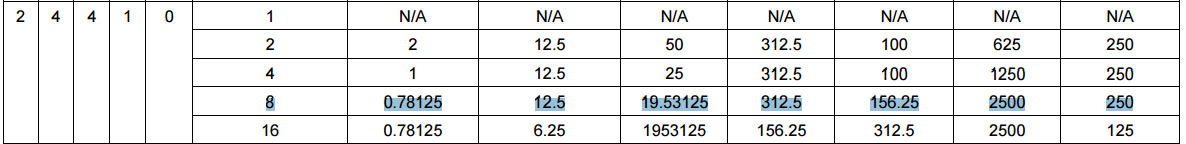
DACCLK=1920MHz

LMF=244

DACA and DACB will generate IQ complex modulated BW of +/-20MHz placed around 360MHz generated by NCO

DACC and DACD will generate IQ complex CW between 250 to 650MHz using the NCO by SPI

The required data rate should be 240MSPS, 

Now for the questions:

1. Is this setup applicable? 

2. How do I know what is the required serdes rate?

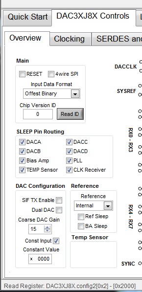
3. Can I generate this setup in the EVM? 

4. What is the maximal rate of the NCO frequency change using SPI? 

5. Is there a VHDL/Verilog block of the DAC?

Thanks

  • Izik,

    If you use an interpolation factor of 1, the serdes rate will be 7.68Gbps. You can use the DAC GUI to come up with this value.

    Are you planning on using the NCO to generate the CW signal and asking how long it would take the SPI to program this? I am verifying that this setup can be done.

    There are no VHDL/Verilog blocks available for the DAC as this is TI proprietary information.

    Regards,

    Jim 

  • Hi Jim

    Looking on table 11 on the data sheet, it looks like the only option for me is

    So I will have to use X8 interpolation. Can you please explain how the serdes rate is calculated

    When I use the NCO mode for DACC and DACD, What is the values of the data lanes? since I don't have any data, I am using only the NCO

    Thanks

  • Izik,

    Based on a int of 8x, the serdes lane rate will be 9.6Gbps. The input data rate will be 240MHz. The shortest time to change the NCO setting would be when using a SCLK period of 100ns. This would take 4 register writes, which would be 9.6us. What do you mean by "What is the values of the data lanes?"

    Regards,

    Jim   

  • When I use only NCO mode,  what value is required in the serdes lanes,  because basically they should be DC.  

    Can you please explain the serdes rate calculation?

    Thanks

  • Izik,

    When using the NCO as an output tone, set the Input Data Format to "Offset Binary" and select the Constant Input box as shown in the attached slide.

    Regards,

    Jim 

    DAC NCO DDS.pptx

  • Hi Jim

    Thank you for your answer. Since I am working simultaneously with the same part that contains four DACs: Two DACs are doing modulation and the other two DACs are working in NCO mode. Is this possible? Will I be able to toggle between the offset binary mode or I can use it during the frames sent to the modulating DACs?

    Thanks
  • Izik,

    The DAC has 2 complex NCOs. 1 for channel AB and 1 for CD. They are independent. Channel AB can have 1 complex frequency and channel CD can have another complex frequency.

    The data format should match what you are sending into the DAC. The NCO just need a full scale signal (DC) to modulate to the output frequency. You can use offset binary or 2s complement. Just make sure you set the right full scale level for that format.

    Ken
  • Ken hello,

    Using data formats offset binary or two's complement, how can the DAC be set to full scale (constant value of all ones or other) using the SPI only, without need of the high speed serdes (JESD 204B).

    We have an application that only constant frequency signal need to be generated, and we want  that the DAC high speed serdes lines will not be connected at all. Is it possible ?

    Thank you

    Menachem

  • Hello Ken

    Can you please help with Menahem's question?

    Thanks
  • Hi,

    You may set the DAC with constant input value.  For offset binary you may use x0000 or xFFFF (min or max value).  

    For 2s complement the min value will be x8000, the max value will be x7FFF.  x0000 and xFFFF are 0 and -1 for 2s complement.

    Ken