This thread has been locked.

If you have a related question, please click the "Ask a related question" button in the top right corner. The newly created question will be automatically linked to this question.

ADS1292R: Schematic design for measuring ECG and Resp. with two leads

Part Number: ADS1292R

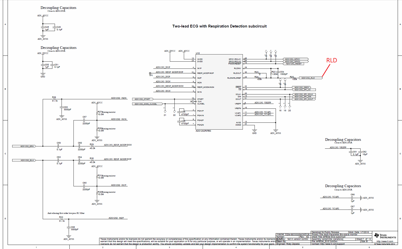
We are trying to measure ECG and Respiratory rate at the same time with ADS1292R but only using the two arm leads(ELA and ERA). We've looked at the suggested application schematics provided in the Evaluation Kit datasheet (attached below), but that design uses all four leads, so how to configure and connect the RLDIN, RLDOUT, and RLDREF pins is one of the problems we have at this stage. 

The other problem we are facing is how to detect lead-off with noise as low as possible. In one of our previous designs, we only used the two arm leads for measuring ECG signals, but the noise for lead-off detection part was so large that we had to make an external lead-off detector through software methods. The configuration is attached here. So is there any ways to configure the lead-off detection automatically using merely the ADS1292R chip under the circumstance that we want to measure ECG and Respiratory rate at the same time using the two arm leads?

Thanks a lot! 

  • Hi Jingyi,

    Welcome to our e2e forum! The ADS1292R configuration you are looking for is basically shown in Figure 56 of the datasheet, where you are using CH1 for the respiration channel and CH2 for the ECG channel with one pair of electrodes. This would require the RLD to set the common mode for the DC coupled channel where you can use DC lead off detection.
  • Hi Tom,

    Thanks a lot for the quick response.

    I found this reference design on TI's website, and that is helpful for our current design process, but we are only wondering where should the RLDREF pin in this schematic go or connected.  Thanks a lot!

  • Hi Jingyi,

    Look through the Design Guide (

    http://www.ti.com/lit/ug/tidu875/tidu875.pdf

    ) specifically on page 8, figures 8 and 9.  The 'nets' shown in the schematic go to contacts on a flex-circuit.  RLD is the one at the bottom in Figure 9.

  • Hi Tom,

    So we are doing the two-lead design, and I think in that design guide there are three. Our product has only two leads in total, so using figure 11 in the design guide but in our two-lead case,  where should the   go?

    Thanks a lot,

    Jingyi

  • Hi Jingyi,

    If you are AC coupling your inputs, you can just leave RLD_OUT floating.

  • Hi Jingyi,
    hum,i have the same problem with you.So i has add another circuit in front of this circuit.But it can't simulate the correct waveform of the heart rate.And i want to ask you that do you solved the problem,can you give me some reference.


    Thanks a lot!


    Lynn