This thread has been locked.

If you have a related question, please click the "Ask a related question" button in the top right corner. The newly created question will be automatically linked to this question.

ADS1220: 2xPT1000 measurement using ADS1220

Part Number: ADS1220
Other Parts Discussed in Thread: ADS124S06

Respected,

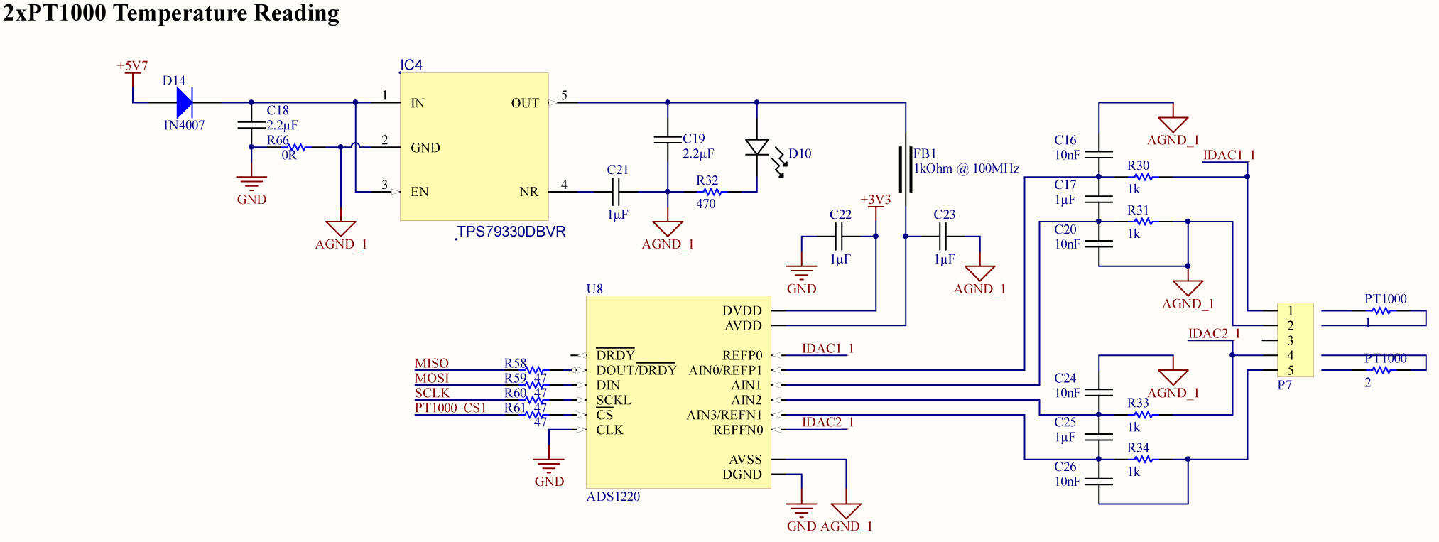
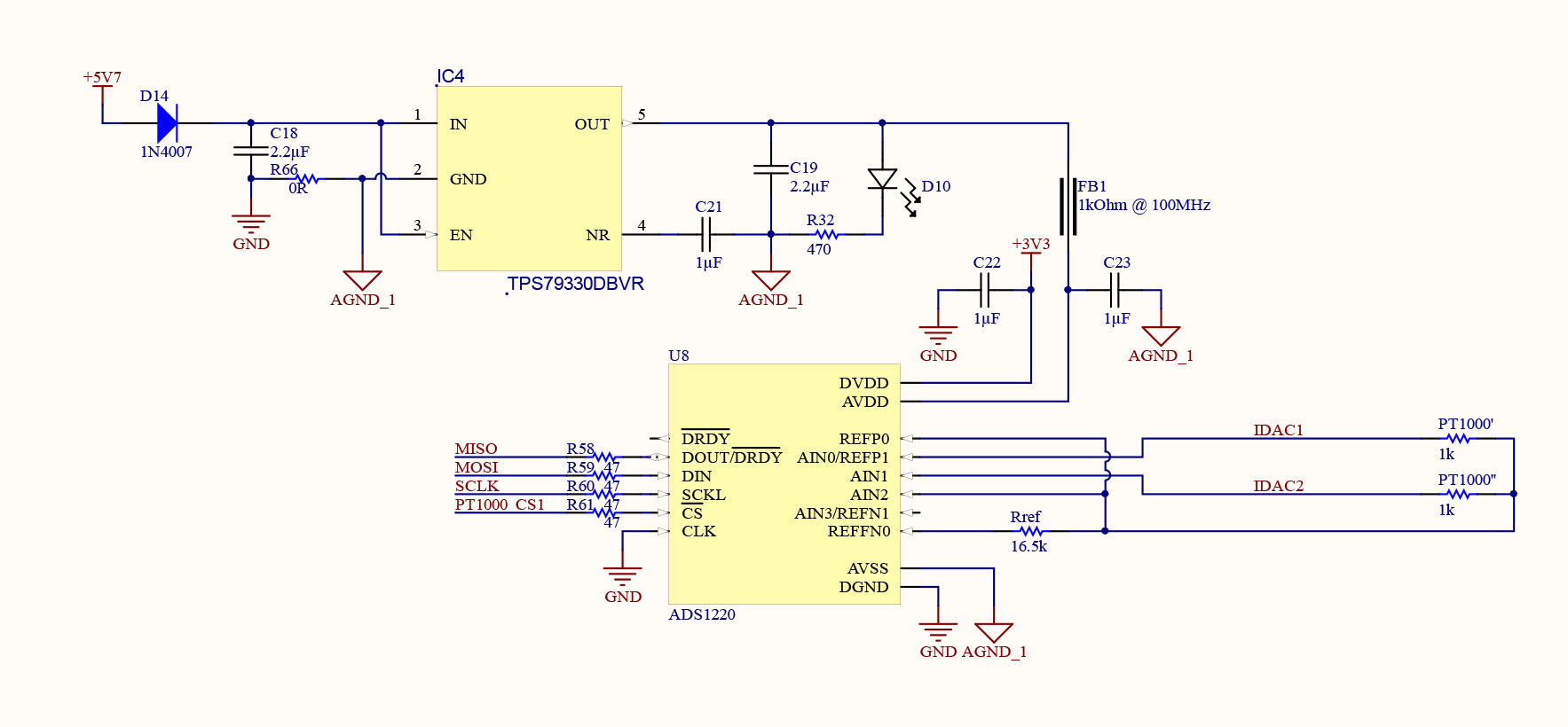
I need to design circuit to measure two PT1000 sensors with one IC  with resolution of 0.01C and accuracy of +-0.1C. Attached I am sending to you the design. I am using its internal 2.048V reference voltage. I need an advice from your experts on how precise (temperature and long term drift) are the internal voltage reference and the IDACs  and will I accomplish my required resolution and accuracy using this configuration?

Many Thanks,

Ilija


  • Hi Ilija,

    Welcome to the forum!  You have a number of things to consider with this design that will prevent you from hitting your target goals.  The first consideration is that it appears you will be using a 2-wire RTD.  Accuracy will diminish as lead resistance will be added into the measurement.  Using a PT1000 (as opposed to a PT100) will help, but the resistance and any effects from the leads will directly impact the measurement.

    Second consideration is your measurement will require PGA disabled (bypassed) as the measurement is take with respect to AGND_1.  This means that the measurement can only have a maximum PGA gain of 4 (which may be ok based on the current you intend to use) but with PGA bypassed you will see an increase in bias current as compared to PGA enabled where the PGA adds an increase in input impedance. Note also I think you are missing a GND symbol at the junction of R34 and C26.

    The third consideration is related to reference drift.  The measurement would greatly improve if a ratiometric measurement were to be made.  A ratiometric measurement would require that the reference for the ADS1220 would come from the same excitation source used by the RTD.  This limits the amount of drift in the measurement result.  Unfortunately the ADS1220 does not have enough inputs to allow a ratiometric measurement for the configuration you wish to use.  You may want to take a look at the ADS124S06 as a device alternative.

    Best regards,

    Bob B

  • Hi Bob,

    Thanks a lot for the in-depth review of my design.

    1 - I am using only two wire design because the length of the wires to the RTD is only 10cm and is constant for each device. The temperature point of interest for accurate measurement is only 37C.

    2 - You are wright, during copy paste AGND_1 was deleted. It is implemented into the original device.

    3 - I thought internal current excitation and voltage reference of the ADS1220 would be more stable than the resistance of the external resistor (Due to temperature drift of the resistor. During experiments I've measured relatively high temperature drift of the 1206 resistor).

    What is the drift of the internal current excitation and voltage reference so I can calculate measurement error and compare later with the ones in the ratiometric measurement.

    Many Thanks,
    Ilija
  • Hi Ilija,

    IDAC drift is shown on page 8 of the ADS1220 datasheet and is typically 50 ppm / deg C.  The reference drift is on page 7, and is typically 5 ppm / deg C, but no worse than 30 ppm / deg C.

    Using a ratiometric measurement with a 10-20 ppm / deg C resistor you should be able to achieve good results.  Any drift of the IDAC will cancel from the measurement as well as much of the noise. 

    Best regards,

    Bob B

  • Thanks a lot Bob for the very useful info,

    I was very curious on how much will measurement differ if ambient temperature rises  20C in current design vs proposed ratiometric design. Attached I am sending to you PDF document with calculation that I've made. Can you please check if my calculations are correct? If they are correct, then ratiometric measurement provides 10 times more accurate measurement.

    Internal current excitation and built in voltage reference vs Ratiometric.pdf

    Also I am sending to you a design that will measure 2xPT100 probes using ratiometric measurement. I removed RC filtering because wires to the probes are very short and very low EMI is present (this is tested on protoboard). Only one probe will be exitated at a time. Do you think that this configuration can be used?

    Best Regards,

    Ilija

  • Hi Ilija,

    If properly implemented you will achieve better performance using the ratiometric measurement method.  You may also find that a 10ppm (or even 20ppm) resistor is good enough as compared to the expense of 5ppm.

    You must make sure you have a current path to AGND, so REFN0 would need to connect to AGND.  You may also find some benefit of having a differential cap across your inputs and the reference.  Even if you don't populate them it is always easier to take something out of the layout than to put it in if the devices become necessary.  Ii would start with 0 ohm filter resistors as well for the same reason.

    Best regards,

    Bob B

  • Hi Bob,

    You are write, I've missed AGND on REFN0.

    Can you please advise me or send me a sketch on how to implement filters? Considering the fact that I am measuring two PT1000 probes (switch them every second and measure one probe at a time). I don't want the capacitance of one channel to affect the other.

    Best Regards,

    Ilija

  • Hi Ilija,

    Adding filter resistors will add some error and adding the caps may degrade analog settling time.  My suggestion is just a suggestion and not a requirement.  As I said, it is always easier to take devices out of a layout as opposed to putting them in.  Having the capacitors as placeholders (DNP) allows you to put them if required.

    This design (as opposed to the previous one) allows you to use the PGA, which helps by increasing the input impedance and reducing the input bias current, so the need of a capacitor as a  charge reservoir is not a primary consideration. You will pickup noise even on short leads or distances unless your system is well shielded from the surrounding environment and from internal system noise from the clocks/signals transition.  The differential capacitors I'm suggesting would go from REFP to REFN and also from AIN0 to AIN2 and AIN1 to AIN2 and you would have to take into account any charge settling between measurements.  If you don't want to use them that is fine.  It is only a suggestion based on my personal experience.

    Best regards,

    Bob B