- Ask a related questionWhat is a related question?A related question is a question created from another question. When the related question is created, it will be automatically linked to the original question.
This thread has been locked.
If you have a related question, please click the "Ask a related question" button in the top right corner. The newly created question will be automatically linked to this question.
Hi Team,
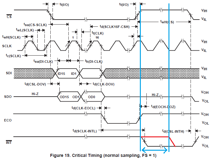
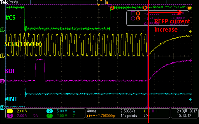
My customer saw REFP current increased from 60uA to 530uA during following blue term (#CS=High, #INT=High).
note) SCLK and SDI inputs (FPGA outputs) shows Intermediate voltage between 0V and 3.3V in this duration because of my customer's system configuration.
Is this REFP increased current possible case for TLC2558?
If you needs additional information or has something unclear, please let me know.
Your support would be appreciated.
Best Regards,
Yaita / Japan disty
Hello,
The input impedance of the reference is switching between a low impedance to high impedance during the time that CS is going from low to high. This may be just from the impedance switching.
I don't think that this is caused by the SCLK and SDI being at an intermediate voltage.
Are they seeing this on all devices? I don't think that it will be a problem.
Mike
Hi Mike-san,
I really appreciate for your support.
I would like to ask additional questions.
>The input impedance of the reference is switching between a low impedance to high impedance during the time that #CS is going from low to high. This may be just from the impedance switching.
1)
Could you tell me the timing when switching input impedance of REFP is occured?
Does it occur just edge timing of #CS low to high or high to low?
2)
I believe REFP shows low impedance when #CS=High.(high impedance when #CS=Low)
Is my understanding correct?
3)
Is the switching input impedance of REFP related to INT state?
I heard my customer found the issue (REFP current is increased) is occured INT=High state only.
Best Regards,
Yaita / Japan disty
Hi Mike-san,
Thank you for your reply.
Could you investigate REFP input impedance under CS=1, SCLK=20MHz(on)?
My customer wants to know if it is possible case REFP impedance decreases less than 20kΩ.
My customer confirmed REFP current increased to 530uA (REFP impedance is approximately1kΩ) from the following red arrow.
He suspects TLC2558 has another switching mode of REFP impedance that datasheet doen't descrbe.
Your support would be really appreciated.
Best Regards,
Yaita
Hi Mike-san,
I really appreciate for your support.
>Can they set up their system so that when CS=1 they pull SCLK low?
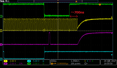
I also heard REFP current increases when SCLK is on more than 700ns from CS=High.
The following pattern doesn't show REFP current increasing because the duration is less than 700ns.
Could you measure from that perspective?
↓ REFP current doesn't increase
>Are they seeing this on all devices?
Yes, my customer confirmed the issue all 30 devices he has.
Best Regards,
Yaita
Hello Yaita-san,
Yes, they can set up their system so that SCLK is low during the times that CS is high.
I will test this when I get the parts. They are on order.
Mike
Hello Yaita-san,
I have received the parts and am trying to get my setup going.
Some questions:
They are saying the reference current is becoming larger during this time. Are they using an external reference?
The listed maximum reference current is 1uA. How are they measuring this to see that it is increasing during this certain portion of the SPI communication? It is difficult to measure this amount of current on a scope. Can they send a scope shot of the SPI communication which also shows the current increasing during the time mentioned.
Thanks,
Mike
Hi Mike-san,
I really appreciate for your continuous support.
I would like to send the information that you need and my customer's schematic in offline.
Could you send e-mail to the following address?
yaita-k@clv.macnica.co.jp
Best Regards,
Yaita