This thread has been locked.

If you have a related question, please click the "Ask a related question" button in the top right corner. The newly created question will be automatically linked to this question.

ADS54J60EVM: Least Significant Byte = Sign bits?

Part Number: ADS54J60EVM
Other Parts Discussed in Thread: ADS54J60, LMK04828

Symptom

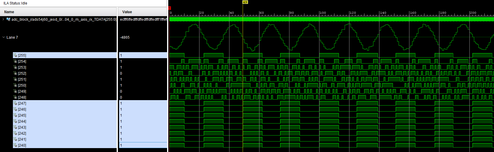
I am noticing something strange in sampled data - least significant byte of the 16-bit ADC samples seems to the same as sign bit! This happens regardless of the amplitude of the signal sent to the ADC, or even when no signal is connected to the ADS54J60EVM input ports.

I wanted to run this by you all in case someone has seen this during their bring up of the ADS54J60. Any ideas why bits [7:0] as highlighted in figure [1] below seem to be exactly the same as bit [15]?

This behavior seems to reduce the resolution, but I am still able to observe a sine wave [3]. 

Configuration

My configuration settings are as follows. I have also attached the two config files that I am using to program the ADS54J60 EVM (LMK04828 and ADS54J60 parts). 

Fs       = 819.2 MHz

LMFS     = 8224

K        = 16

Subclass = 1

SYSREF   = 3.2 MHz (Enabled)

Figures

[1]

[2]

256-bit output from Xilinx JESD204 core at 102.4 MHz. 8 lanes x 32 bit datapath = 256 bits

[3]
LMK_Config_Onboard_819p2_MSPS.cfg

ADS54J60_LMF_8224.cfg

  • Terraxion,

    Are you following the power up sequence per the data sheet? If so, can you send me the complete register map you are loading into the device? By any chance, did you program the registers to have the OVR going to the LSB? If this is so and you are over driving the input, I could see these two data bits track each other. 

    Regards,

    Jim

  • Thanks for the quick reply Jim.

    I am using the ADS54J60EVM, so I'm using the following sequence:

    1. Load LMK config file for 819.2 MHz. 
    2. Press SW1 reset after observing PLL2 locked led turn on. 
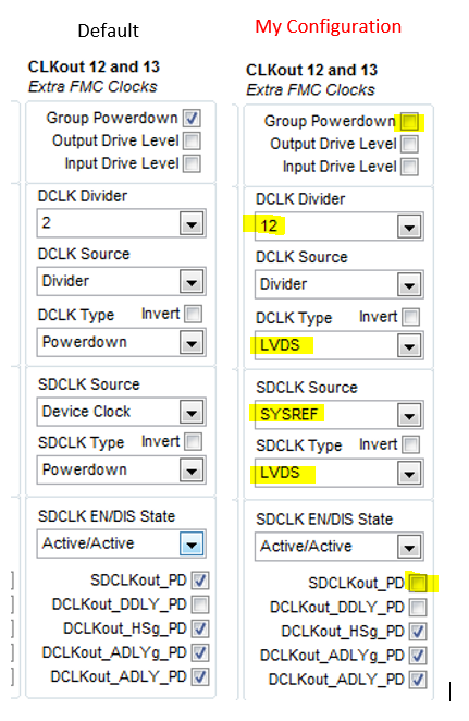
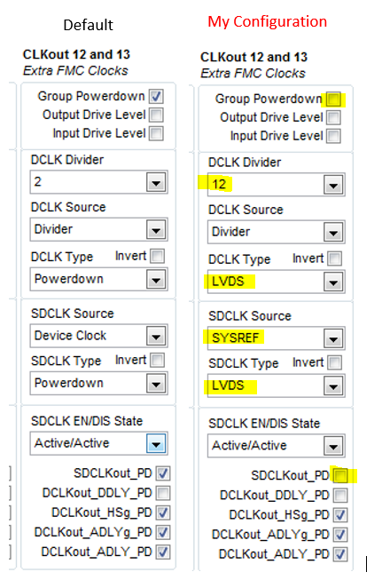
      1. Under LMK04828 Tab, turn on CLKout 12 and 13 (Extra FMC Clocks). See [1]. 
    3. Load ADS54J60 config file for LMF8224. 

    I attached the two config files that I use in my previous post but let me attach the config file generated by the GUI v1.8 after doing the "Read All" action. See below [2].

    Since I am using the GUI + default config file to program ADS54J60, I don't think the OVR related registers are getting programmed to send OVR bit on LSB. I can do a read of those registers let me know which ones?

    For example if I want to read register 0x59 in Master Page, would i select "ADS54JXX_DIGITAL" from the Block options and type in "8059" into the address field?

    [1] LMK Configuration changes

    [2] Readback of registers as reported by GUI v1.8

    Signed-LSByte-Readback.cfg.cfg

  • Terraxion,

    You have several problems with your ADS54J60 register settings. Please use the following in place of your settings:


    ADS54Jxx_ANALOG
    0x0000 0x81  //  LMF = 8224
    0x0011 0x80
    0x0059 0x20 // always write 1 to bit 5
    ADS54Jxx_DIGITAL
    0x6800f7 0x01 // digital reset
    0x680000 0x01 // reset digital
    0x680000 0x00 // clear reset
    0x690000 0x80 // set CTRL K
    0x690006 0x0F // set K to 16

    Many of the default settings are used in this mode so you only need to program the registers shown above.

    Is this a custom board? Wondering why you are changing the LMK output clock settings.

    Regards,

    Jim

  • Settings

    After using your settings, I still observe the same behavior. 

    I had to append the following line at the beginning of the register setting you mentioned in order to get data flow:

    LMK04828
    0x10F 0x66 //Enable SYSREF to ADC

    LMK

    No custom hardware - I am using the ADS54J60EVM connected to ZCU102 via FMC connector. 

    The LMK output clock setting is changed to enable 204.8 MHz "global clock" going into FPGA logic. 

    RPAT

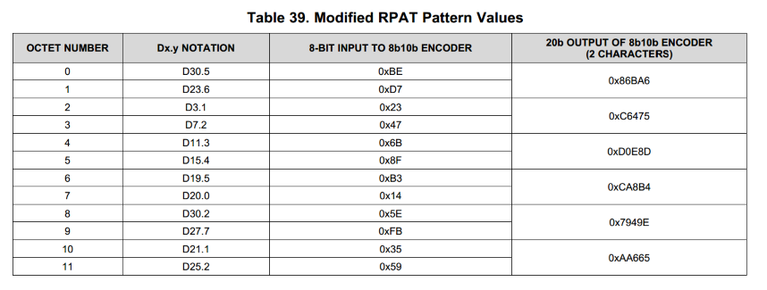
    In 12-octet RPAT test mode, I receive all 12 bytes, and all bits toggle as expected.

  • Terraxion,

    We have tested this family of parts with a ZC706 platform and have example firmware available under the TSW14J10EVM product folder on the TI website. Attached is an example setup using the 12 bit version of this ADC. We are working on example firmware for the KCU105 that should work with the ZCU102. This should be available in about 1-2 weeks.

    Regards,

    Jim

    ZC706 ADS54J20 8224 Setup.pptx

  • This turned out to be a red herring (false alarm), all bits coming out of the ADC are as expected.The fix was swapping the MS and LS bytes!

    In conclusion, using ADS54JXX GUI v1.8 to program the ADS54J60EVM with default configuration settings files corresponding to 819.2 MHz, LMFS 8224 is confirmed to work with ZCU102.

    Thanks Jim for your help and prompt responses in this and other threads!