This thread has been locked.

If you have a related question, please click the "Ask a related question" button in the top right corner. The newly created question will be automatically linked to this question.

ADS1231: Noise performance and characterisation

Part Number: ADS1231

Hello.

I have converted the data from my full bridge load cell using the ads1231 adc and an Arduino Nano. My setup is the same as the application example pg16 data sheet attached below with 3.04V AVDD and 3.1V DVDD.
The problem is I am not sure if I am getting good or bad noise performance etc (I have attached some of my results below at no load, loaded in the positive and negative direction with the maximum load for that load cell 5kohm.
1. I cannot see how you obtained the conversion data in nV for Noise vs. Time data on page 7 of the data sheet could someone help with this? could you please help in how I can convert my values to the same scale?
I know to convert my decimal values to a voltage it is Vin = Output Code * LSB Size. LSB = 1.49*10^-9 (FSR/2^24bit)
and FSR is Vref/gain (3.04/128) Which means for example at no load output code is 341000 * 1.49*10^-9 = 0.49mV (Which is the same as my measured Vinpp-Vinn)
2. If you can verify that my data is okay then I can work changing the excitation voltage to 5V (if I change AVDD&VREFP to 5V and keep DVDD at 3V, does this violate the common mode requirements?)
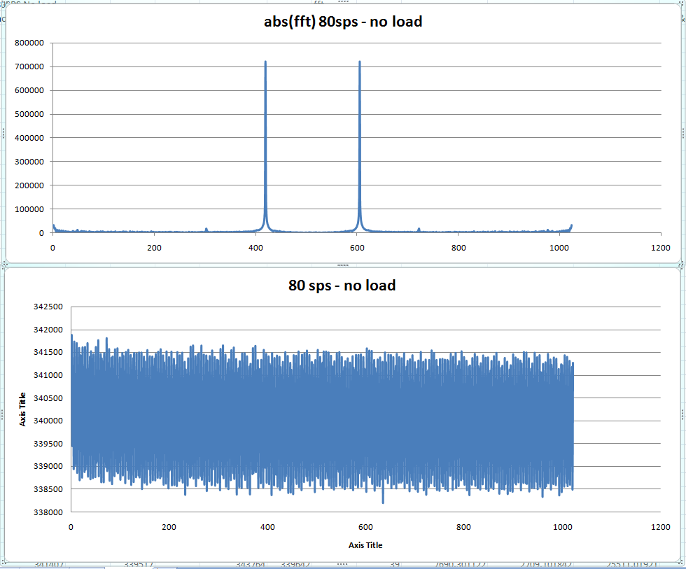
3.  Another thing is my data for 80sps seems too consistent and repeating a similar pattern & I do not know if this is to do with my power supply frequency or how I am obtaining the data? how can I get rid of that so that the data is more similar to the data sheet.
  • I have done the FFT for the 80sps no load results which appear with the results being periodic, I get two peaks on the 395th and 419th samples frequency 30.85Hz & 32.75Hz but I am not sure what that means. I am guessing I am getting some external noise somewhere? or could it be how I am obtaining the results like a coding issue?
  • Hi Kev,

    In another thread you asked about converting the differential output data of the ADS1231 to a unipolar format.  I think that this is part of your confusion with the data appearing as mV instead of nV.  I think it would be easier to use the codes directly output from the ADS1231 for the calculation instead of converting them to unipolar. 

    For the noise tables in the datasheet, the input is shorted together at mid-AVDD supply.  The amount of noise is determined from the peak to peak difference in codes from 1024 samples. The formulas used are shown directly above Table 1 on page 6. If you reverse the calculations you can see the number of noise codes.  Operating at 3V and 10sps, the noise-free codes is 16.8.  Total resolution is 24, so the noise is 24-16.8 which is 7.2.  2^7.2 is about 147 codes peak to peak.  This is a huge difference from the 1000 code no-load condition.  80sps will be worse, but not by 10000 codes.  So you need to find the source of the noise.  At 80sps no-load, there appears to be about 40 samples within one complete cycle which equates to about 2Hz.  This can be some low frequency vibration or possibly from aliasing.  Do you have any input filtering?  Also noise can be picked up along cabling as the cable acts as an antenna.  Eliminating noise from the measurement is not a trivial task and can be the most complicated part of the whole system design.

    As far as the supplies, AVDD and DVDD can be different voltages.  Common-mode requirements relate only to the analog inputs and AVDD.

    Best regards,

    Bob B

  • Thank you for your reply. No I do not have any input filtering. I do have some long cables and using a breadboard to wire everything. If the ideal P-P noise is 147 codes and as you mentioned the 1000 and 10000 I am getting at 10 sps and 80sps are bad what kind of numbers should I expect to see from a typical good system, that uses a breadboard & an Arduino? so I know what to aim for.

    *This can be some low frequency vibration or possibly from aliasing*
    What kind of steps can I take to get rid of this?
  • I have placed a 1uF cap between AINPP and AINPN and also I was using a DMM which I think was giving me some of the noises. Now I just get the 1 peak at about 31.5Hz (420th sample). Are there any areas I could have a look at to eliminate this? and does my data look more acceptable now? I get about 2400-3000 codes and using your calculations in a near perfect system like in the data sheet this should be 2^(24-15.4) = 388 codes. 

  • Hi Kev,

    You should be able to achieve very close to the datasheet numbers even with the breadboard system assuming that your prototype is cleanly dressed on the breadboard without having long wires and leads exposed.  This takes some effort.  If your have a bunch of wires crossing, long leads and a noisy environment then it is anybody's guess as to what you might expect.  Power line-cycle noise can be picked up from lighting and this may be a contributor.  Try adding 1k series resistance to each of the analog inputs prior to the differential capacitor.  This should help eliminate any aliasing.

    I would suggest simplifying the setup as much as possible.  Perhaps checking your noise first with a voltage divider at mid-AVDD and the inputs shorted to the mid-AVDD connection.  This would be the best you would be able to achieve.  If you are still seeing issues then you need to discover the source.  Make sure all supply connections are adequately bypassed at IC devices in your setup.

    Best regards,

    Bob B

  • Hi. Thanks for the reply.

    1. I am not sure I understand what you mean or how to go about it - " Make sure all supply connections are adequately bypassed at IC devices in your setup."

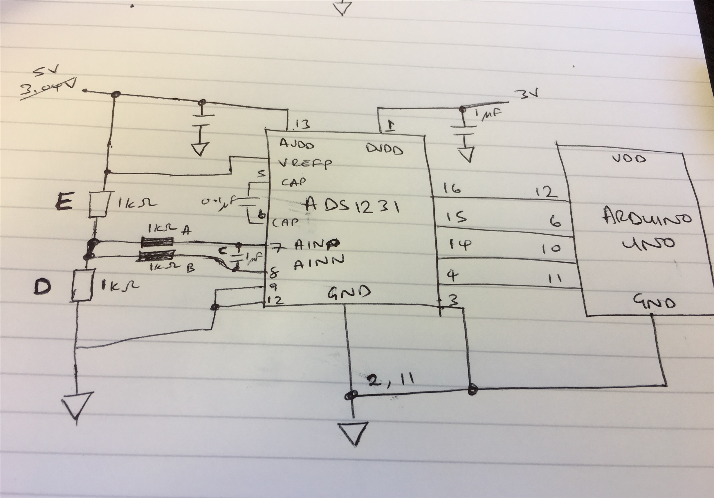
    2. "I would suggest simplifying the setup as much as possible.  Perhaps checking your noise first with a voltage divider at mid-AVDD and the inputs shorted to the mid-AVDD connection" I have attached my connection diagram could you please verify that this is okay? I will not be using resistors and cap labeled A,B&C for this simplification. so AINPP and AINN will be connected directly between resistor D&E

    3. I will be using a full bridge sensor (As described in the data sheet application instead of resistor D&E). Resistors A,B and Cap C will be connected to the inputs as shown on the diagram. 

    Does this seem like what you have described?

  • Hi Kev,

    See my responses below.

    Best regards,

    Bob B

    kev M said:

    Hi. Thanks for the reply.

    1. I am not sure I understand what you mean or how to go about it - " Make sure all supply connections are adequately bypassed at IC devices in your setup."[Bob B] These caps are the caps near the device supply pins.  So this looks ok in the drawing.

    2. "I would suggest simplifying the setup as much as possible.  Perhaps checking your noise first with a voltage divider at mid-AVDD and the inputs shorted to the mid-AVDD connection" I have attached my connection diagram could you please verify that this is okay? I will not be using resistors and cap labeled A,B&C for this simplification. so AINPP and AINN will be connected directly between resistor D&E [Bob B] I would suggest trying it both with and without the filter components to see if there is any noise pickup due to the filter.

    3. I will be using a full bridge sensor (As described in the data sheet application instead of resistor D&E). Resistors A,B and Cap C will be connected to the inputs as shown on the diagram. 

    Does this seem like what you have described? [Bob B] Yes.  One other thing I should mention is the cap at pins 5 and 6 is extremely sensitive.  A high quality cap should be used and when breadboarding use very short leads.

  • Hello.

    I have connected AVDD = DVDD = VREFP = VDD = 5V (using the same DC Power supply) and VREFN=SW=GND and connected the AINP and AINN to Mid AVDD as shown on my previous post. The results I get are negative but I am not sure why the negative offset? Ignoring that, I have attached the results below & If the calculations you showed me earlier are anything to go by then I am getting quite close to the full 17.4 bits noise free at 10 sps and 15.9 noise free bits @80 sps. (I get p-p 303 codes and 114 codes which are 17.16 and 15.76 noise free bits). If all this is okay, does that mean the noise is coming from the bridge sensor? since that is the only thing I have replaced or there is more to it than that?

    ti noise.xlsx 

  • Hi Kev,

    The result data does show a negative offset. but that is ok.  The ADS1231 datasheet states that the offset is typically 10uV.  This can be thousands of codes offset, so if you are seeing only a few hundred that is pretty good.  Also, when connecting and calibrating the sensor, the offset is easily removed.

    As far as the FFT, I didn't run through all the calculations, but I don't really believe what is shown.  Based on Nyquist, the bandwidth is 5Hz and 40Hz, or one half of the output data rate.

    Your noise is close to what to expect, so most likely the noise is being picked up at the sensor or within the cabling of the sensor.

    Best regards,

    Bob B