This thread has been locked.
If you have a related question, please click the "Ask a related question" button in the top right corner. The newly created question will be automatically linked to this question.
Hello,
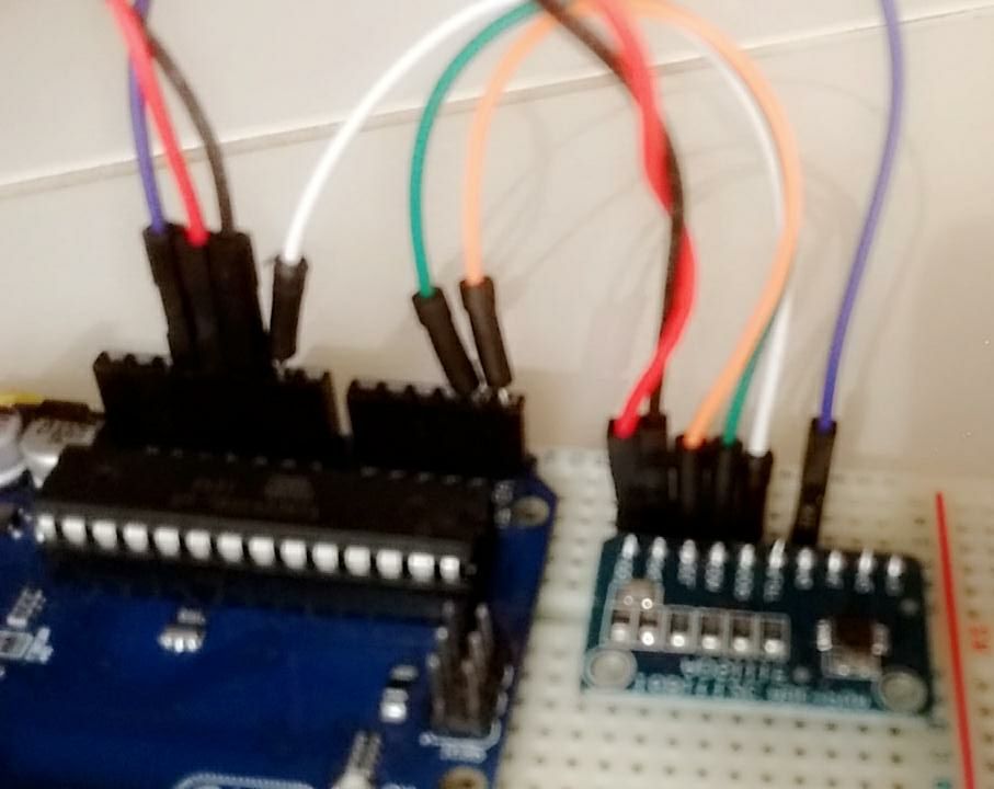
I have two ADS1115 and attempting to use with Arduino UNO board.
I'm following instructions presented on https://learn.adafruit.com/adafruit-4-channel-adc-breakouts.
Arduino Library from Adafruit is used and can be download on https://github.com/adafruit/Adafruit_ADS1X15
I'm tryed to read voltage from Arduini +3.3V but all I get from the code is "-1" as value.
AIN0: -1 AIN0: -1 AIN0: -1 AIN0: -1 AIN0: -1
I've searched on several sources and what I could see is that if I get a "-1" value is probably an i2c problem.
What is wrong?
I've testes with 2 different ADS1115 and both gives me the same result.
The .ino code is presented as follows.
Files .ccp and .h from my library is attached to this post.
#include <Wire.h> #include <Adafruit_ADS1015.h> Adafruit_ADS1115 ads(0x48); void setup(void) { Serial.begin(9600); Serial.println("Hello!"); Serial.println("Getting single-ended readings from AIN0..3"); Serial.println("ADC Range: +/- 6.144V (1 bit = 3mV)"); ads.begin(); } void loop(void) { int16_t adc0; adc0 = ads.readADC_SingleEnded(0); Serial.print("AIN0: "); Serial.println(adc0); Serial.println(" "); delay(1000); }
Yes, I've already seen that. It's the guide I've cited on the post, but in a web version.
1. The device is being powered by +5V from arduino and i confirmed with multimeter directly on the device pins.
2. It is connected to ground.
3. I do not have tools for that, I need to provide one for me.
So, i tryed to send a simple code to the configuration register and read it back to see what happnes.
The code i used is presented above.
Accordingly to datasheet I have to send the code to access the configuration register (00000001 - 0x01) followed by the configuration I want (1100111010000011 - 0xCE83). Then to read I send the code to access the configuration register and close, request 1 byte, get it and print. (https://www.arduino.cc/en/Reference/WireRead)
#include <Wire.h> void setup() { Serial.begin(9600); Wire.begin(); } void loop() { Serial.println("Start writing"); Wire.beginTransmission(0x48); Wire.write(1); Wire.write(0xCE83); Wire.endTransmission(); Serial.println("End writing"); Serial.println("Start reading"); Wire.beginTransmission(0x48); Wire.write(1); Wire.endTransmission(); Wire.requestFrom(0x48, 1); byte valor; if (Wire.available()){ valor=Wire.read(); } Wire.endTransmission(); Serial.println("End reading"); Serial.println(valor); delay(1000); }
The result I get is 0
Start writing End writing Start reading End reading 0 Start writing End writing Start reading End reading 0 Start writing End writing Start reading End reading 0
Eduardo,
Let me first say that I don't do much coding, so I may not be able to help much in debugging Arduino code. However, can you try this instead:
Wire.beginTransmission(0x48);
Wire.write(0x01);
Wire.write(0xCE);
Wire.write(0x83);
Wire.endTransmission();
I think Arduino code breaks the transmission up into byte transactions, so split up the write into bytes.
Reading back from the device, just remember the configuration register is two bytes. You'll want to read back 2 bytes, not 1.
However, if you continue to get back 0, I think you'll still need to get some sort of oscilloscope or logic analyzer. At this point, there's no way to know if the signals are coming out of the Arduino to talk to the ADS1115.
Joseph Wu