This thread has been locked.

If you have a related question, please click the "Ask a related question" button in the top right corner. The newly created question will be automatically linked to this question.

ADS1299: Impedance measurement issue when the input of one pin are separated to three channels

Part Number: ADS1299

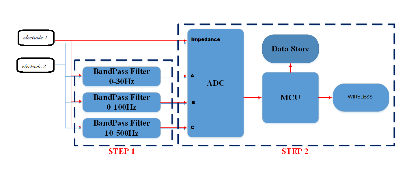
I am trying to measure the lead impedance using AC lead-off detection (6uA, 31.2Hz). The attached file shows the diagram of my electrode connection to the circuit. Specifically, the signal transferred from the single electrode to one pin (e.g., pin 1) will be input into 3 different channels (e.g., channel 1, 3, and 5) in the ADC. Moreover, before digitizing the signal, I also add different analog filters and amplifiers corresponding to each channel in front of the Analog-Front-End (AFE) IC. Summarily, in my design, there are 3 channels used to receive and process the single input and 1 channel used to measure the impedance of that single electrode.

As a result, I currently have 2 problems: (1) the measured impedance is incorrect and (2) the measured signals of interest are also affected by noise comes from the channel which is used to measure impedance. Could you help me know

1. What are the reasons of these problems? (My thoughts for problem (1) and (2) are that the three channels mutually affect and the measured signals are affected by noise coming from the channel used to measure the impedance, respectively.)

2. Is there any possible solution to help overcome these problems without changing the design of my board?

0654.Circuit Design.docx

  • Hello Anh,

    Thanks for your post.

    I don't see where the ADS1299 is connected in your schematic. Do you have a complete schematic in PDF format that you can share instead?

    At a high level, I think you might be adding unnecessary complexity to your design. The main goal of a heavily integrated IC like the ADS1299 is to simplify the system design and reduce the need for additional, discrete amplifiers or filters. Are you averaging the 3 channels together? The ADS1299 features 8 simultaneously sampling channels that can be averaged together in post-processing if the noise is not already low enough. Also, with additional amplifiers in the signal path, you will not be able to measure the electrode impedance.

    Best Regards,
  • Hi Ryan,

    Thank you for your replies to Lan Anh questions. I am working with Lan Anh on that project. Please take a look at the schematic of the hardware and the functional diagram - "System Diagram.png"

    We would like to separately take out three types of signal which has different range of frequency and different voltage level. Therefore, we think of making band pass filter which has different filter and gain factor.  We also leave one channel for measuring impedance of the electrodes - as indicated in "System Diagram.png"

    The hardware was completed. The measurement results showed that:

    + When measuring impedance alone, the result was accurate.

    + When we used all of these four channels for measurement - impedance and signals of interest, the impedance is not correct and noise affected signals of other three channels.

    + When we only measured the signals of interest in three channels (A, B and C), there was still noise.

    Can you please review? Please let me know if there is any solution which we can both measure the impedance of electrodes and separately  pre-process the signals from these electrodes with filter and amplifier while keep the noise level at minimum.

    Thanks,

    Quyen

    Schematic design.pdf

  • Hi Quyen,

    Thank you for providing the PDF and block diagram. It is a little more clear to me now.

    I think this problem has more more do this with the active bandpass filters than the ADS1299 itself. I'm not an amplifier expert, but I'll try to provide some guidance here from a general ADC perspective. Otherwise, more investigation is probably needed into the signal conditioning part of your design.

    1. For starters, try to short the electrode inputs together and measure the noise on each channel. That will give you a good indication of the expected noise performance in each path and whether the signals your wish to measure can be seen above the noise floor.
    2. Next, try to force a known signal from a function generator and compare the differences on each channel. It looks like a 30-Hz sine wave could work for all 4. Remember to share the function generator ground with your circuit ground. If you cannot pass a sine wave through, configure the ADS1299 to use the internal square wave test signal and verify the device registers are set appropriately.
    3. How are you comparing the results of the "Impedance" channel alone vs. all channels? Are you powering-down Channels A, B, and C? There should be minimal crosstalk between channels on the ADS1299 itself, so something from your amplifiers must be loading/coupling the Impedance channel. Try disconnecting the electrodes from the three active filters, then reconnect them to one filter at a time.
    4. Feedback on ADS1299 schematic:
      1. The START pin is floating. If you want to control START with the SPI command, tie this pin low. Otherwise, tie it high to DVDD.
      2. The BIAS amplifier feedback path is incorrect. The output of the BIAS amplifier (BIASOUT) should connect to BIASINV (the amplifier inverting input). This connection should take place after the 1M || 1nF. BIASIN is used either to provide an external common-mode (BIASREF) voltage or to route BIASOUT into the MUX. Leave BIASIN floating if unused.

    If you would like us to review your register settings for the ADS1299, feel free to post them below and we can review them as well.

    Hope this helps!

    Best Regards,