Hello Team,
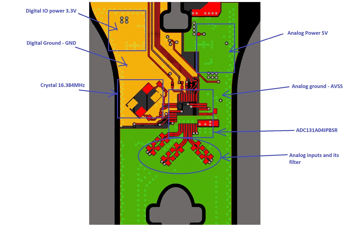
We are using ADS131A04IPBSR ADC in our design, and its been operated in single supply (+5V) mode. We have connected AVSS (pin 10) to Analog ground plane and GND (pin 27) to Digital Ground plance. Both are tied together at common point using 0 OHM resistor.
Could you please suggest if this approach is good for ADC performance ?
Can we get PCB layout file of ADS131A04EVM to verify the ground connectivity ?
The placement and layout is shown in the picture below,


