


Other Parts Discussed in Thread: ADS1292R
HI:
When using ADS1291, I have the following questions:
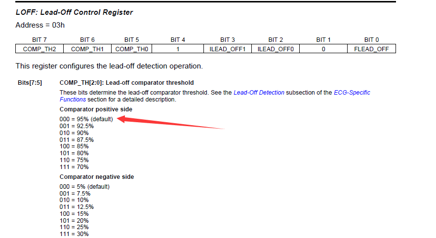
1. What is the value of 95% in the red arrow in the figure below? Which 95% of the value?
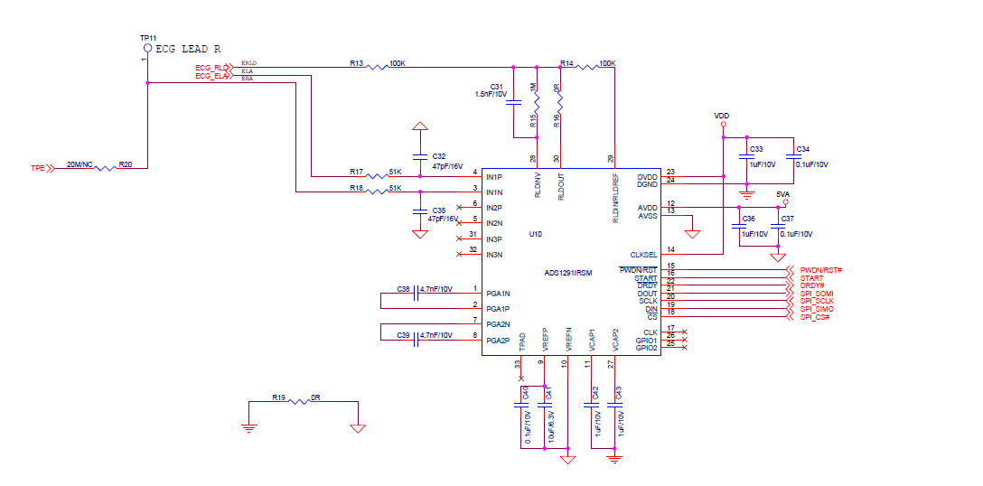
2.I can now collect the ECG signal of the ECG simulator. There is a QRS wave, but I can't acquire the ECG signal on the arm. When I collect the ECG signal from the human body,
what are the major parameters to adjust? The schematic is as follows:
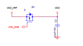
3. There is a question about DVDD power,When VDD_EN is enabled via the GPIO port, VDD has 3.3V supply, but using a multimeter to test the DVDD of ADS1291,
the voltage is only 2.74V. This should be abnormal? Should be 3.3V normal. What should I pay attention to when powering up?
I refer to the ADS1292R reference design example for power-up mode,the TI DEMO"tidcbr3.zip".
think you !
