This thread has been locked.

If you have a related question, please click the "Ask a related question" button in the top right corner. The newly created question will be automatically linked to this question.

ADS1220: ADS1220 nonlinear behavior in negative measurements at high temperature.

Part Number: ADS1220
Other Parts Discussed in Thread: REF3230,

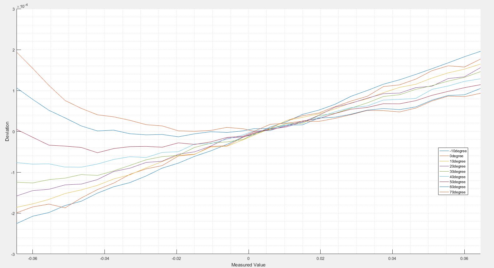
I'm using ADS1220 and REF3230 to measure between -60mV and 60mV. Also I want the resolution to be 0.015uV. So, I set the ADS1220 gain to 32. I calibrated the linear curve I obtained at room temperature. But in negative measurements at high temperatures, the curve is parabolic. 

What is the reason of this. Thanks.

  • Hi user5254233,

    Your circuit, setup and system may be very clear to you, but I need a lot more detail about your system before I can be of help. Can you send me your schematic and how you are connecting your source voltage? What is the common-mode voltage of the input voltage? Which analog inputs are you using?

    Make sure that you are following the common-mode range restriction equations 13 through 15 on page 22 of the ADS1220 datasheet. The input range will change depending on gain applied.

    Best regards,
    Bob B
  • Hi Benjamin,

    My schematic and the deviation graph are below. Analog inputs are AIN0 and AIN1. Other analog inputs are used for another measurement. So you don't take them into account. 

    As you can see in the graphic, deviations in negative measurements increase with increasing temperature. In negative values at high temperature, why are curves nonlinear?

    Best regards,
    Mustafa.

  • Hi Mustafa,

    Thanks for the additional information.  Can you also send me more information on portion that is labeled RTD_SHUNT_IN_A and RTD_SHUNT_IN_B?  Are you using a PT100 RTD?  And how are you exciting the RTD?  Can you also send me the register settings you are using for the ADS1220?

    Usually when we see this type of behavior it is either due to increased input leakage at higher temperatures which creates a voltage drop across the input filter resistor creating a measurement error.  Or by operating outside of the input common-mode operating range.  As we only see this behavior on the negative side, I believe the issue is operation outside or very close to the input common-mode limit.  To verify, you can measure the AIN0 to AGND and AIN1 to AGND at -60mV input to determine your input common-mode.  Another indicator would be to try lowering your gain to see if the problem goes away.  The common-mode restriction gets narrower with increased gain.

    Best regards,

    Bob B

  • Hi Bob

    I have two ADS1220s in my design. I use it to measure other ADS1220 PT100. That is, P1 and P2 can be used for two different measurements. However, IC101 is not used when measuring CURRENT_ADC_A and CURRENT_ADC_B. Also RTD_CURR_SELECT is 0V and R1011 is not connected.

    The other part of the design:

    IC91 register settings:

    static const struct Ads1220Config ads_curMeas_cfg = {

    .mux = ADS1220_MUX_AIN0_AIN1,
    .gain = ADS1220_GAIN_32,
    .pga_bypass = 0,

    .rate = ADS1220_RATE_330_HZ,
    .conv = ADS1220_CONTINIOUS_CONVERSION,
    .opmod = ADS1220_OP_NORMAL,
    .vref = ADS1220_VREF_EXTERNAL_REF,
    .fir = ADS1220_FIR_NONE,
    .idac = ADS1220_IDAC_OFF,
    .i1mux = ADS1220_IMUX_OFF,
    .i2mux = ADS1220_IMUX_OFF

    };

    Best regards,

    Mustafa

  • Hi Mustafa,

    Just so that I am clear, you are making a measurement using a current shunt with IC91, is that correct?  One of the problems with net labels on a schematic is it becomes hard to follow the total path of a signal when you are not familiar with the design.

    Even if a device is schematically open, there can still be leakage paths which I think is part of the issue.  Another consideration is that it appears the shunt is floating as I see no relationship to AGND.  Your shunt should have some relationship to AGND or it is possible for the shunt to float out of the common-mode input range of the ADS1220.

    One thing I missed earlier is IC91 is powered by a bipolar supply and is operating outside of the recommended range (see section 6.3 in the ADS1220 datasheet).  Although it is not specifically stated, the ADS1220 will work best with symmetrical supplies (i.e. +/- 2.5V).  This is implied in section 6.3 in the bipolar analog supply section under POWER SUPPLY where the nominal is set to +/- 2.5V.

    Your initial graph shows a relationship to the internal reference value (2.048V) but your register setting shows external reference which is 3V.  Verify that your calculation is using the correct reference voltage value.  FSR for 2.048V and gain of 32 is +/- 0.064V and for 3V is +/- 0.09375V.

    Best regards,

    Bob B