This thread has been locked.
If you have a related question, please click the "Ask a related question" button in the top right corner. The newly created question will be automatically linked to this question.
HI TIs.
Our team used ads1299 to do EEG measuring about 2 years.
we have many difficulties. our system is a 24-channl EEG. We found our PC software show some bad wave like the following figure.
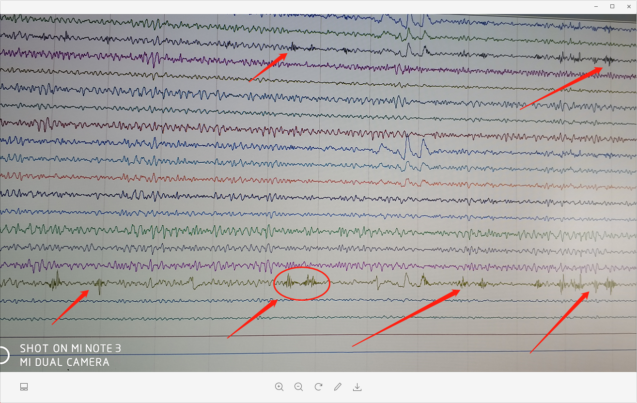
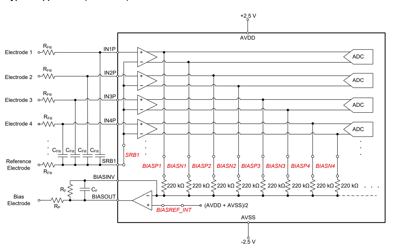
we use the montage in datasheet Figure 73.and Filter set Digital Bandpass =1Hz-70Hz Wave Limiter=50Hz。RC= 4.99K and 4.7nf ,bias RC=1M and 1.5nf
So, how can we do to make our sys better. This problem will be Make doctors makeWRONG judgments .
Help. I need help from your from TI.
THK.
LINDA
Hi.
Think you for your reply.
As you said. We have tried to find the problem.
When we do the input impedance test, Similar situation we found.
We add a RC model bettwen our system and sin single generator.
R = 620K . C=47nF.
This test is used to measure the input impedance.
We are very surprised at our test results.This value is about 10M(No lead-off).
This is much smaller than the value provided in the datasheet(min=1000M).
So We don't know what is wrong we did?
We want to konw how do you get the value(1000M), What instrument is used,and how?
At last ,Here we are very sorry that only some schematics are provided.
More schematics are being organized. we will updata later.
And can you show me your email address,Some file transfer will be more convenient
Thinks
LIN DA