This thread has been locked.

If you have a related question, please click the "Ask a related question" button in the top right corner. The newly created question will be automatically linked to this question.

TSW14J57EVM: Trigger Option

Part Number: TSW14J57EVM
Other Parts Discussed in Thread: ADC12J4000EVM, ADC12J4000, LMK04828

Is it possible to use an external trigger with the TSW14J57EVM connected to the ADC12J4000EVM? Has this feature been implement yet?

Some other forum posts from awhile back seem to indicate that the firmware does not have external trigger support on the newer TSW14J57EVM (https://e2e.ti.com/support/data_converters/high_speed_data_converters/f/68/t/620008?tisearch=e2e-sitesearch&keymatch=TSW14J57EVM%20trigger

  • Hi Andrew
    Can you check the version of your TSW14J57EVM?
    The firmware included in the most recent version of High Speed Data Converter Pro (v4.90) should support trigger functionality with the TSW14J57EVM Rev. E board.
    Best regards,
    Jim B
  • Hi Jim,

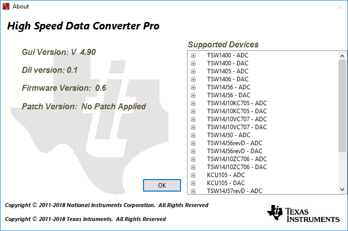
    I have Rev E of the TSW14J57EVM. According to the about screen, it looks like i'm running firmware version 0.6. 

    Unfortunately the "Trigger Option" menu item is disabled under the "Data Capture Options" menu.


  • Hi Andrew
    Which ADC12J4000 operating mode are you using? What ADC/mode are you selecting from High Speed Data Converter Pro?
    I may need to send you a modified .ini file to enable triggering for that mode with this new firmware.
    Best regards,
    Jim B
  • Hi Jim,

    I am using ADC12J4000_BYPASS mode.

    Thanks,
    Andrew
  • Hi Andrew

    Please try this new .ini file. 

    /cfs-file/__key/communityserver-discussions-components-files/73/0572.ADC12DJ4000_5F00_Bypass_5F00_trig.ini

    Download and copy it into the following directory location:

    C:\Program Files (x86)\Texas Instruments\High Speed Data Converter Pro\14J57revE Details\ADC files

    Once you've done that, launch High Speed Data Converter Pro. After the ADC EVM is configured select this file as the ADC/Mode "ADC12J4000_Bypass_trig". Download the firmware and set the ADC output sample rate as you normally would.

    The trigger option in the menu should be enabled and trigger should work. Note that the firmware used for capture only uses internal FPGA memory, so capture depth is limited to around 512k samples.

    Let me know if this works, or if you have any problems. I don't have a Rev E board at my disposal so haven't verified this exact combination.

    Best regards,

    Jim B

  • Apologies for the delay in testing this out. This file seems to work, but I have a few additional questions about it.

    1. Is there any documentation on the functionality of the various paramters .ini files such as:

    Trigger Input Polarity Selection = 1
    Trigger Output Default State = 0
    Trigger Output Pulse Width = 40
    Sysref Based Master Slave Trigger = 0
    Is Capture Trigger SMA = 1

    Specifically, what does "Sysref Based Master Slave Trigger " do?

    2. According to this .ini file, the system is operating in JESD204B Subclass 1. However, on probing the SYSREF signal going from the LMK04828 to the ADC on the ADC12J4000EVM board, it appears that this signal is disabled. How is Subclass 1 synchronization possible without this signal?

    3. Is it possible to take the SYSREF or LMFC signal from the system so that I can precisely synchronize external hardware with the beginning of a capture period?

    4. The lane rate (in HSDC Pro) with the original ADC12J4000_BYPASS.ini file was 10G (4G sample rate). The lane rate changes to 8G using the ADC12J4000_BYPASS_trig.ini file. Why would it be different? Also, since I used the same settings in "ADC12J4000EVM GUI A" in both cases, shouldn't the ADC lane rate be the same in both cases?

    Thanks,

    Andrew

  • Andrew,

    The attached INI File Guide has a description for each of the trigger related parameters.


    2.       According to this .ini file, the system is operating in JESD204B Subclass 1. However, on probing the SYSREF signal going from the LMK04828 to the ADC on the ADC12J4000EVM board, it appears that this signal is disabled. How is Subclass 1 synchronization possible without this signal?


    The ADC can operate without SYSREF but the output will not have deterministic latency.


    3.       Is it possible to take the SYSREF or LMFC signal from the system so that I can precisely synchronize external hardware with the beginning of a capture period?


    SYSREF Based Triggering feature aligns ADC Capture and external hardware with a SYSREF aligned trigger. It has two modes- SYSREF based Master triggering and SYSREF based slave triggering. Please refer the INI File guide for more details. But we don’t have this feature supported in J57revE Firmware yet.


    4.       The lane rate (in HSDC Pro) with the original ADC12J4000_BYPASS.ini file was 10G (4G sample rate). The lane rate changes to 8G using the ADC12J4000_BYPASS_trig.ini file. Why would it be different? Also, since I used the same settings in "ADC12J4000EVM GUI A" in both cases, shouldn't the ADC lane rate be the same in both cases?


    Lane Rate Adjustment Factor=0.8’ parameter is added in ADC12J4000_Bypass_trig.ini file and not in the original Ini file which is causing the difference in lane rate calculation shown in HSDC Pro. This parameter needs to be added for BYPASS mode lane rate calculation, to calculate effective number of bits transmitted excluding tail bits

    Regards,

    Jim

    TSW14J57 ADC INI File Guide.doc