This thread has been locked.

If you have a related question, please click the "Ask a related question" button in the top right corner. The newly created question will be automatically linked to this question.

ADS114S08: How to measure four 3-wire RTDs

Part Number: ADS114S08
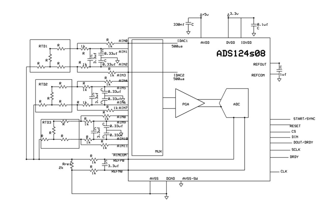
I was having a look at this schematics and have a few questions. I do not fully understand why those 1k resistors are used on the Idac channels and why there is no common mode filtering on the reference channels?

I have planned to use the ADS114S08 for measuring 3 wire RTDs and this is how I plan to connect them it is very similar to this configuration. Only differences would be I have used  diodes on Idac channels for protecting reverse currents, common mode filtering for the reference channels as well. I have also kept the cutoff freq for the analog filter low since I would not be able to make use of the digital filter's 50/60Hz rejection at 60SPS or greater. 

I am posting the modification of the schematics for my application. Please guys let me know if I am right.

Thanks a lot.

Harini

  • Hi Harini,

    The 1k ohm series resistor is to limit possible reverse current. This is sometimes done instead of the diode as you have shown. Generally you would do one method or the other as every device in series will have a voltage drop associated with it.

    The filter values can be chosen that best suites your needs. The most important cap is the differential cap, and the higher quality the better for both stability and noise. For example a C0G/NPO cap is a better choice than an X7R. The grade of cap desired may not have a the desired grade for the size/value chosen, so this will be a tradeoff.

    There may not be a need for common-mode caps at all. This will be determined by the environment the system operates in. For a discussion on filtering for RTDs, see the application note SBAA201.

    Best regards,
    Bob B