This thread has been locked.

If you have a related question, please click the "Ask a related question" button in the top right corner. The newly created question will be automatically linked to this question.

ADS42JB49: Unable to lock LMK04828 on ADS42JB49 EVM

Part Number: ADS42JB49
Other Parts Discussed in Thread: LMK04828, ADS42JB69

Hi,

I have a setup with ADS42JB49, TSW14J10 and KC705. 

I followed the ADS42JB49 user guide and installed ADS42JBxx software. I have loaded the configuration file ADS42JB49_EVM_LMF421_250M.cfg that comes with installation.

The LMK LOCKED led on the board is always blinking and PLL2 LOCKED led is ON. 

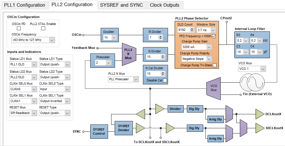
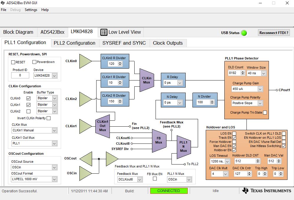
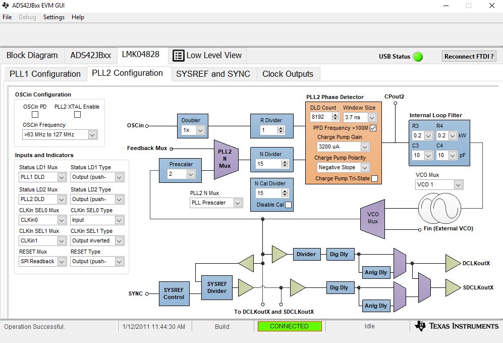
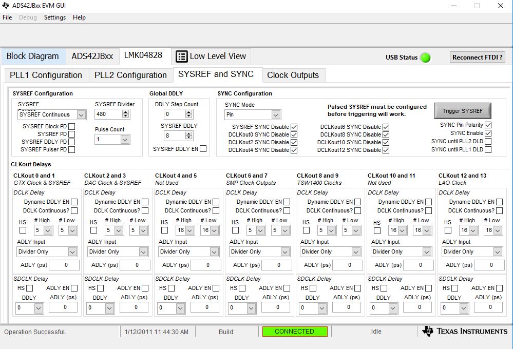
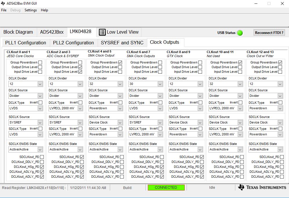
Below is the PLL1 configuration

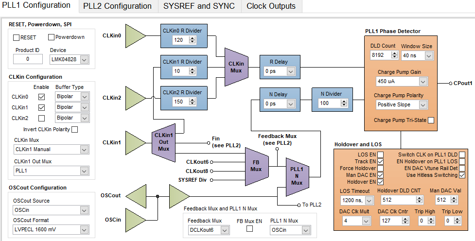
I am using the on board VCXO. Do I need to update any other parameters for LMK04828?

Thanks,

Yogitha

  • Yogitha,

    In the box labeled as "PLL1 N Mux" (in the bottom of the GUI), change the setting to "Feedback". In the "Holdover and LOS" box, disable "Use Hitless Switching". Make sure jumper JP5 has the shunt installed between pins 1-2 and JP2 has a shunt between pins 1-2.

    Regards,

    Jim 

  • Jim,

    Thanks for the quick response.

    I tried the things you mentioned but it didn't help. When I change the PLL1 N MUX to feedback the LMK LOCKED led is going OFF.
    The jumpers JP5 and JP2 are properly set.

    Regards,
    Yogitha
  • Any help on this issue? I couldn't figure this out yet.

    Thanks,

    Yogitha

  • Yogitha,

    I just ran this evm with the GUI default configuration with no problems. Please check your settings with the ones attached. You must press the board reset after power up and before you load the configuration file. What revision is the EVM you have?

    Regards,

    Jim

    ADS42JB49.pptx

  • Hi Jim,

    I configured the EVM with the same settings you shared but still the LMK LOCKED led is always blinking. 

    By board reset do you mean the switch SW4 (LMK RESET)? After power on I press this reset and then load config file.

    However, once the EVM is configured and then I press this SW4 I don't see any any difference with the led status (D4 ON, D1 Blinking). I am using Rev D board.

    Below are the configuration settings

    Thanks,

    Yogitha

  • Yogitha,

    Not SW4, SW1 (ADC reset). You need reset the ADC, not the LMK. Press this after power up and before loading the configuration file.

    Regards,

    Jim

  • Hi Jim,

    I pressed the SW1 - ADC reset before loading configuration and still the Led's status is same.

    Thanks,
    Yogitha
  • Yogitha,

    Very that R19 is installed (back of board near LMK device. Shares pad with C74) and that 10MHz is present on both sides of this resistor. If the LMK is getting 10MHz and LED D4 is turning on, then there might be a problem with the LMK device. The board will still work without this 10MHz reference. Do you need the VCXO to be referenced to the on-board 10MHz oscillator?

    Regards,

    Jim

  • Hi Jim,

    I checked that R19 is properly installed. There is an 100MHz oscillator present which is connected to the OSCINP pin of the LMK04828 and the D4 led is always ON after configuration. We do not have an external clock source right now, so need to reference the on board oscillator.

    How can I figure out the problem with the LMK and get it working?

    Thanks,

    Yogitha

  • Yogitha,

    You did not answer my question regarding the 10MHz oscillator. This board has both an 100MHz VCXO and an 10MHz oscillator. Do you see 10MHz on R19 when using an oscilloscope? The 10MHz is only used to lock the 100MHz VCO to this 10MHz. It is not required for the LMK to operate properly.

    Here is another test to try;

    1. Power up the board, press the ADC reset switch, then load the conf file called "ADS42JB69_EVM_LMF421_250M.cfg".

    2. Click on the LMK04828 tab, then the Clock outputs tab.

    3. Uncheck the "Group powerdown for CLKout 6 and 7.

    4. Change the DCLK Type for CLKout 6 to "LVPECL 2000mv". Change the DCLK divider for this output to 30.

    5. You should now see 100MHz on SMA J10. If not, I think you may need to get a replacement board.   

    Regards,

    Jim

  • Hi Jim,

    I generated a 100Mhz clock on SMA J10 and connected it to KC705. Through signal tap I could see a decent clock on the FPGA port. I will confirm the clock quality using the oscilloscope. I will also confirm the 10MHz clock on R19  soon.

    But then if the clock is properly generated on J10 does that mean the LMK is working fine?

    Thanks,

    Yogitha

  • Hi Jim,

    I have generated the clock on SMA J10 and connected it to KC705. Through signal tap I observed that a stable clock is received at FPGA port. I will confirm the quality of clock using the oscilloscope. Also on the 10Mhz clock on R19 I will confirm with the scope soon.

    But then if the SMA J10 clcok is properly generated does that mean LMK is working fine and that ADC and FPGA clocks will be properly generated?

    Thanks,

    Yogitha

  • Yogitha,

    I think your LMK is working fine. Does your setup look like the one in the attachment? Do you have the ribbon cable installed between the TSW14J10 and the KC705? When you open HSDC Pro GUI, are you able to load the firmware in the FPGA? If so, what is the status of the LED's on the KC705? If the firmware is not loading, send me screen shots of the HSDC Pro GUI.

    Regards,

    Jim

    KC705.ppt 

  • Hi Jim,

    I have checked the R19 installed on back of the board. I could see 10MHz clock on both sides of the resistor. I have followed the steps you have mentioned to generate 100MHz clock on ClockOut6. I see a ~248Mhz clock instead of 100. For whatever divider value I set for the clock, it always generates 248MHz clcok.

    Below are the oscilloscope snapshots.

    Clock on both sides of R19

    DclockOut6 with divider set to 30

    Thanks,

    Yogitha

  • Yogitha,

    In the GUI, there is a LMK04828 tab. Click on this then send me screen shots of every tab under this one. Then send the register settings for the ADC and LMK that you are using by going to the Low Level View and clicking on "Save Config".  While in the Low Level View tab, did you verify you can write and read properly to the registers in both parts?  

    Regards,

    Jim

  • config_file.cfgHi Jim,

    Please find the screenshots below

    I was able to verify the Register read and writes through GUI. 

    Thanks,

    Yogitha

  • Yogitha,

    Everything looks fine as far as I can tell. You may just have a bad board. See the link below regarding EVM exchange/returns.

    Regards,

    Jim

    www.ti.com/.../faq-returns-and-refunds.html