This thread has been locked.

If you have a related question, please click the "Ask a related question" button in the top right corner. The newly created question will be automatically linked to this question.

DAC7716: DAC7716 SPI Problem

Part Number: DAC7716

Hello, 

We are trying to generate the SPI input for the DAC from an FPGA board.

So far we have tested our waveform against the Clock. (SCLK)

SCLK has 10MHz Frequency. The address of the SPI register is 0100, the data we are sending is "111111111111". 

The Chip select goes high for one clock cycle after 24 bits are sent and Latch goes low when Chip select goes high. 

But we are not able to see any output from the DAC outputs. 

Is there any other thing that should be taken care of?

When we plot the waveform that are going to the DAC chip in MATLAB, we can see that the setup time is negative (i.e. Data comes a little later than the rising edge of the clock)

Also, how can I make sure that the setup and hold time requirements are met in the Inputs.   

  • Hi Aeishwarya,

    Welcome to E2E and thank you for your query. The data is sampled at the falling edge of the SCLK.

    Could you please upload a scope shot of the SPI waveforms? You can also try at a lower SCLK like 100kHz or so in order to make sure there are no signal integrity issues.

    Regards,
    Uttam Sahu
    Applications Engineer, Precision DACs
  • Hi Aeishwarya,

    Do you have any update on this?

    Regards,
    Uttam
  • Hello Mr. Sahu,

    Thank you for your reply. I Apologize for the delay.

    According to the Data sheet for the DAC chip, the data is to be updated on the positive edge.

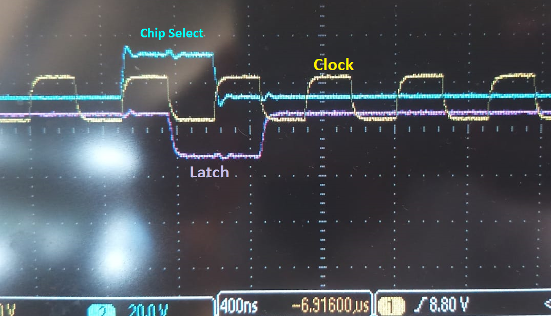
    We still did the test with negative edge, I have attached an Oscilloscope screen shot below.

    We are providing only one address to check at least on one of the output channels.

    Best Regards,

    Aeishwarya Baviskar

  • Hi Aeishwarya,

    Please look at the following:
    1. Data should be stable during falling edge of the SCLK
    2. Check whether you are respecting t9 (gap between CS rising edge and LDAC falling edge)
    3. You are using a continuous clock and looks like you are using 24 clock cycles for every update. So, ideally t7 should not come into picture. But if nothing works, please look into it

    I think if you take care of (1) and (2) and if needed, (3), it should work.

    Also, please try a slower SCLK to start with.

    Regards,
    Uttam
  • Hello Mr. Sahu,

    Now the Waveforms to the DAC look like the following,

    Figure 1

    1. Data is stable during falling edge

    2. t9 between chip select (sky blue) and Latch (green) is satisfied. We are using 1,8V scale so according to the data sheet t9 is min 30ns

    Figure 2. One Complete cycle for Chip select and Latch.

    Figure 3. Close look at chip select and Latch.

    Is there still something that I am missing ?

    Best Regards,

    Aeishwarya Baviskar

  • Hi Aeishwarya,

    The SPI pattern looks fine. However, the register address you are sending is "0010" instead of "0100". This makes the command invalid. Please correct that and check again.

    Please let me know if there is still an issue.

    Regards,
    Uttam
  • Hello Mr. Sahu,

    The address bits were indeed not configured properly.

    So we corrected those and tried with a slower clock also.

    Figure 1. With clock frequency 2MHz (white stripes for counting)

    Figure 2. Clock Frequency 200kHz

    We changed the address input to 0101 just to check if the first channel was damaged.

    Unfortunately, we still cannot see any analog output out of the DAC output pin.

    Kindly advise if we are missing on something else.

    Best Regards,

    Aeishwarya Baviskar

  • Hi Aeishwarya,

    We need to look at the hardware. Could you please upload the schematics?

    In case you are concerned about confidentiality, you can send the schematics to my mail id through private message.

    Regards,
    Uttam
  • Hi Aeishwarya,

    Do you have any update on this?

    Regards,
    Uttam
  • Dear Mr. Sahu, 

    We found a mistake in our code, which solved the problem. Now, every port is working. 

    Your comments were very helpful during the process. 

    Best Regards, 

    Aeishwarya Baviskar