This thread has been locked.

If you have a related question, please click the "Ask a related question" button in the top right corner. The newly created question will be automatically linked to this question.

ADS1298: Noise issue for ECG device with data rate @500sps

Part Number: ADS1298

Dear all,

  We are using ADS1298 board in our Patient monitoring product.

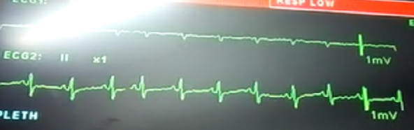
Normally in battery condition, the wave-forms are perfect.

whenever try to connected power cord to unit total ECG wave-forms are collapsed.

Kindly suggest how to reduce this type of interference by using internal filter or protection ,otherwise we have to implement any digital filters.

Thanks,

Guna S R

  • Hello Guna,

    Thanks for your post and welcome to the forum!

    Is this question in regards to this post?

    e2e.ti.com/.../700035
  • Hi Smith,

      That is related with cautery noise issue it seems. Here we have power line interferrence noise issue without cautery diathermy device. Shall we continue with this threat?

    Kindly help us with this issue

    This image is 3 pin power cord connected

    This image is 2 pin power cord connected


    Guna

  • Hi Guna,

    Thank you for the clarification.

    A 2 pin power cord does not have a ground connection. The noise appears to be caused by the system not having sufficient connections to ground.

    Can you provide a schematic? If you are not comfortable posting the schematic online, with your permission I can contact you through email.
  • Hi Smith,

     Good morning. Have a great day.

    Not an issue to share schematic with you.Since already one of my colleague was shared schematic about noise signal generated when human body is touched. Please find out the link below: https://e2e.ti.com/support/data_converters/precision_data_converters/f/73/p/556323/2037700?keyMatch=dinu&tisearch=Search-EN-Everything.   Please go through above link and help us to sort out the issue.

    Thanks,

    Guna

  • Hi Guna,

    I hope you are well.

    I agree with Brian that the schematic looks good.

    The signal improves significantly with the addition of a ground connection from the power cord. When the cautery device is used there is significant interference that appears to be introducing itself into the signal path instead of being passed to ground properly.

    Due to these two reasons I believe these issues are caused by a deficiency in how the system itself is grounded. This could be due to board layout or system construction. To debug this issue I recommend adding robust ground connections at various points throughout the system and see if there is an improvement. If you post your layout and/or provide any information on the system grounding I can suggest some points to test.

    Signal isolation could be an issue as well, but that would require a more intensive board re-design.
  • Hi Smith,

    Thank you for your reply.

    Let me tell you one think, actually we were using proper ground connection. In PCB we have a separate layer for ground connection so that

    here the screenshot of pcb layout added and the register settings and schematic of ADS1298R.

    Please verify the register settings is correct or not. I have a doubt with RLD_SENSP & RLD_SENSN register so that please verify it and

    Is there i used individual channel for RLD?

    Whether i want to connect the inputs to the RLD through high impedance resistors ?

    For 5 Lead

    write_ads1298r_reg(W_CONFIG1 , 0X86);

    write_ads1298r_reg(W_CONFIG2 , 0X20);

    write_ads1298r_reg(W_CONFIG3 , 0XDC); //0XDE

    write_ads1298r_reg(W_LOFF , 0X03); //lead 5

    write_ads1298r_reg(W_CH1SET , 0X50);

    write_ads1298r_reg(W_CH2SET , 0X50); // Set all channels to input short

    write_ads1298r_reg(W_CH3SET , 0X50);

    write_ads1298r_reg(W_CH4SET , 0X50);

    write_ads1298r_reg(W_CH5SET , 0X50);

    write_ads1298r_reg(W_CH6SET , 0X50);

    write_ads1298r_reg(W_CH7SET , 0X50);

    write_ads1298r_reg(W_CH8SET , 0X50);

    write_ads1298r_reg(W_RLD_SENSP , 0X02);

    write_ads1298r_reg(W_RLD_SENSN , 0X06);

    write_ads1298r_reg(W_LOFF_SENSP , 0XFF);

    write_ads1298r_reg(W_LOFF_SENSN , 0X02);

    write_ads1298r_reg(W_LOFF_FLIP , 0X00);

    write_ads1298r_reg(W_LOFF_STATP , 0X38);

    write_ads1298r_reg(W_LOFF_STATN , 0X00);

    write_ads1298r_reg(W_GPIO , 0X00);

    write_ads1298r_reg(W_PACE , 0X00);

    write_ads1298r_reg(W_RESP , 0XF2);

    write_ads1298r_reg(W_CONFIG4 ,0X22);

    write_ads1298r_reg(W_WCT1 , 0XFA);

    write_ads1298r_reg(W_WCT2 , 0XE3);

    For 3 Lead

    write_ads1298r_reg(W_CONFIG1 , 0X86);
    write_ads1298r_reg(W_CONFIG2 , 0X20);
    write_ads1298r_reg(W_CONFIG3 , 0XDC);
    write_ads1298r_reg(W_LOFF , 0X13);
    write_ads1298r_reg(W_CH1SET , 0X00); // According to the condition of test signal
    if(node== 1)
    {
    write_ads1298r_reg(W_CH2SET , 0X50); //for lead 1
    write_ads1298r_reg(W_CH3SET , 0X56);
    }
    else if(node==2)
    {
    write_ads1298r_reg(W_CH2SET , 0X56); ////for lead 2
    write_ads1298r_reg(W_CH3SET , 0X50);
    }
    write_ads1298r_reg(W_CH4SET , 0X50);
    write_ads1298r_reg(W_CH5SET , 0X50);
    write_ads1298r_reg(W_CH6SET , 0X50);
    write_ads1298r_reg(W_CH7SET , 0X50);
    write_ads1298r_reg(W_CH8SET , 0X50);
    write_ads1298r_reg(W_RLD_SENSP , 0X06);
    write_ads1298r_reg(W_RLD_SENSN , 0X02);
    write_ads1298r_reg(W_LOFF_SENSP , 0X06); //oxoe three positive //0x06 for two positive signal//oxF6//0xff pasitive lead detection (select by 1) //second f9 //0X0E //0xff
    write_ads1298r_reg(W_LOFF_SENSN , 0X02); //0x02 negative lead signal detection off(select by 1) //second f9 //0X0E //0x02
    write_ads1298r_reg(W_LOFF_FLIP , 0X00);
    write_ads1298r_reg(W_LOFF_STATP , 0XF9); //0x38 lead stues for positive ( select by 0)
    write_ads1298r_reg(W_LOFF_STATN , 0XFB); //lead staus for negative lead (select by 0)
    write_ads1298r_reg(W_GPIO , 0X00);
    write_ads1298r_reg(W_PACE , 0X00);
    write_ads1298r_reg(W_RESP , 0XEE); //oxEE(phase value 90 ) //0xF2(phase value 112.5),,0xF6(phase value 135),//respiration with internal frequency
    write_ads1298r_reg(W_CONFIG4,0X22); //0x22//respiration and lead of comparator enbled
    write_ads1298r_reg(W_WCT1 , 0XFA); //lead selection for right arm and aumented lead
    write_ads1298r_reg(W_WCT2 , 0XE3); //lead selection for LL and LA


    GunaT12A.xlsx4251.SCHEMATIC1 _ ECG_ADS1768R.pdf

  • Hi Guna,

    I do not see an issue with the RLD configurations.

    Having a ground layer on the PCB is a great practice, however there appears to be a lot of segmentation. Since I do not know where the return currents are being generated from and where the GND is ultimately connected to the chassis, it is impossible for me to assess if every connection is sufficient.

    Can you highlight where the major sources of return path current will be and where the chassis GND connection is?