This thread has been locked.

If you have a related question, please click the "Ask a related question" button in the top right corner. The newly created question will be automatically linked to this question.

ADS1292R: ADS1292R

Part Number: ADS1292R

Hello,

I am designing a ECG Front-End board based on ADS1292R chip and I would like to add the "Shield Driver". This is NI (Not Installed) in the Reference Design (slau384a) from Texas Instruments.

In other thread of E2E forum this topic was discussed and in the last post, a circuit based on opa 333 operational amplifier was proposed. The post shows the resistors that can be added to configure the amplifier as inverter or non-inverter. I attached the circuit. (e2e.ti.com/.../584828)

My questions are the following:

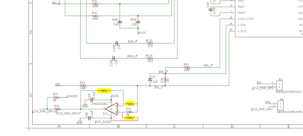
1. When does the amplifier should work as an inverter and when as non-inverter?
2. When the amplifier is configured as an inverter. Why the (+) amplifier's input is connected to the resistor and this is connected to ADS_AVDD? I don't understand this part of the circuit. I think that the output can be saturated.

Thanks

Julio

  • Hi Julio,

    Thanks for your post.

    I agree with your suspicion - in the non-inverting configuration, I do not see any reason why the the non-inverting input would be connected to the supply pin through a resistor. That looks like a mistake, in my opinion.

    We've learned through some customers that the shielding should contain the same common-mode signals as the input electrodes. Because the RLD output contains the inverted common-mode, it may be necessary to invert the signal again before driving the shield. The inverting amplifier configuration uses the DC voltage at the non-inverting input to set the output common-mode. Typically, this is near mid-supply, just like the internal RLD amplifier itself.

    Best Regards,