This thread has been locked.

If you have a related question, please click the "Ask a related question" button in the top right corner. The newly created question will be automatically linked to this question.

Sourcing Current Monitor solution

Other Parts Discussed in Thread: INA226, INA219

Hi,

This is david from Unionmem, Now we are looking for a sourcing current monitor solution. The requirement is :

measurement range:5~40mA

Accuracy:10uA

we need this solution to measure the current consumption of another low power IC.

we can measure the current value just like 5.26mA,20.67mA etc.  and hope we can measure the current clearly in time

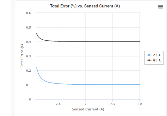
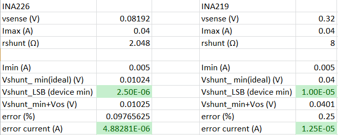
we have ever found the solution INA226,ina219 on TI website, but we're not sure the two solution can meet our requirement, please kindly help to  check and suggest your solution to us, tks!

Regards,

David Hu

  • Hello David,

    Thank you for considering to use Texas Instruments in your design.  To determine whether these devices will work, we need to be familiar with the typical error for these device as well as their resolution.  Below I have a figure of a typical error curve for a current shunt monitor device (you can actually see these curves on the right-side of the product page, INA226 one here).  Your error curve will likely have a similar shape yet the values will be different based on your operating conditions.  In this curve you may notice that lower currents have the highest error.  The error that dominates this region is the offset error.  As this will be the chief factor that will determine whether you can achieve 40uA resolution (especially for low currents), this is what I will be analyzing below.  However, there are other sources of error that can contribute to the total error and if you would like to know about those, I would recommend watching this training video.

    In my calculations below I take take the max Vsense (Vshunt) voltage listed in the datasheet and your max expected current (40mA), to determine what shunt resistor will yield the highest resolution or accuracy.  Thereupon I use this value with your minimum system current (5mA) to determine the smallest voltage you intend to have across the shunt when the device is powered.  From there, I check to see that this value is above the device LSB (found in the datasheet) to ensure that the device can actually measure that low.  Once the ability to measure the lower limit is verified, I add the max expected voltage offset (from datasheet) to get the worst case expected voltage seen at the input.  I then use this value to determine the error.  Thereupon from the error I calculate the error current, or how much excess error may be observed compared to what should ideally be seen.  From these calculations,  I believe both devices will work. 

    /cfs-file/__key/communityserver-discussions-components-files/73/1832.INA219INA226.xlsx