This thread has been locked.

If you have a related question, please click the "Ask a related question" button in the top right corner. The newly created question will be automatically linked to this question.

ADS1298ECGFE-PDK: ADS1298 PGA setting

Part Number: ADS1298ECGFE-PDK

Hi,

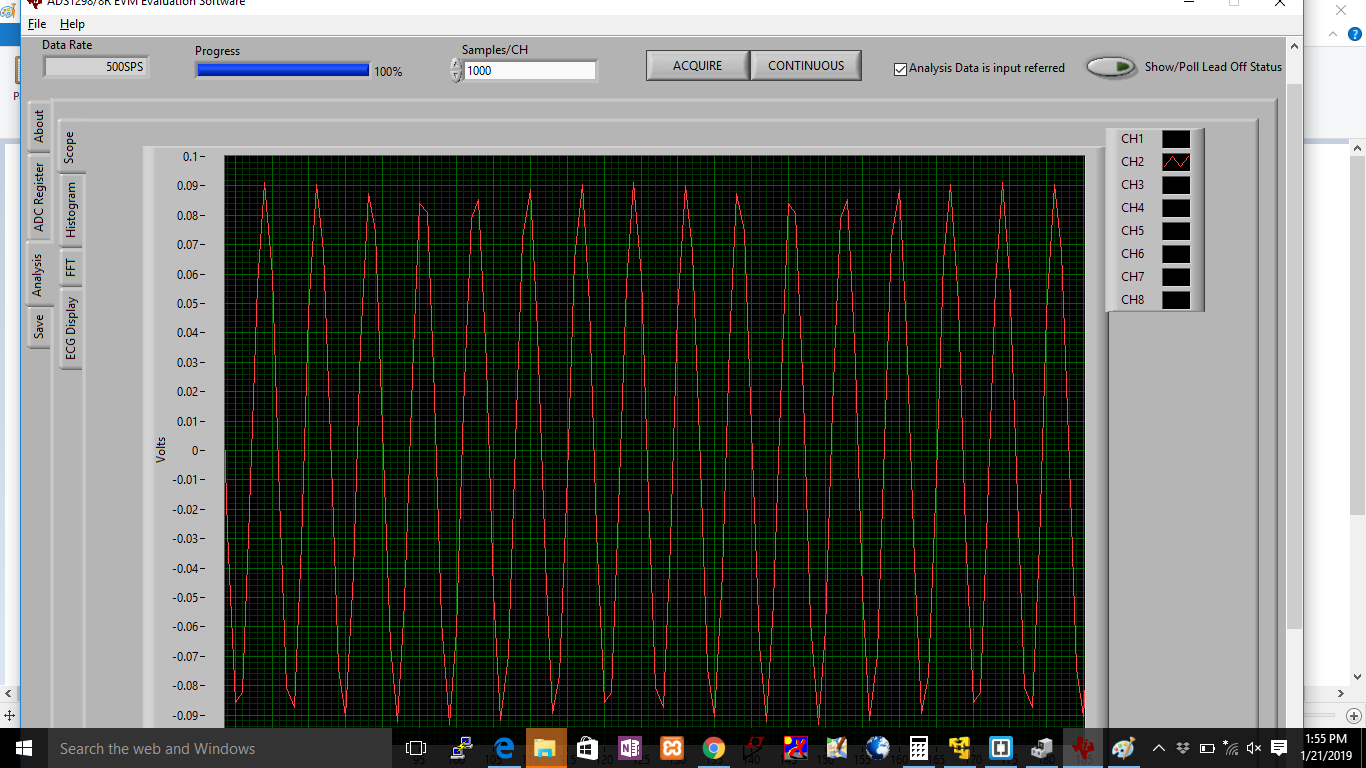
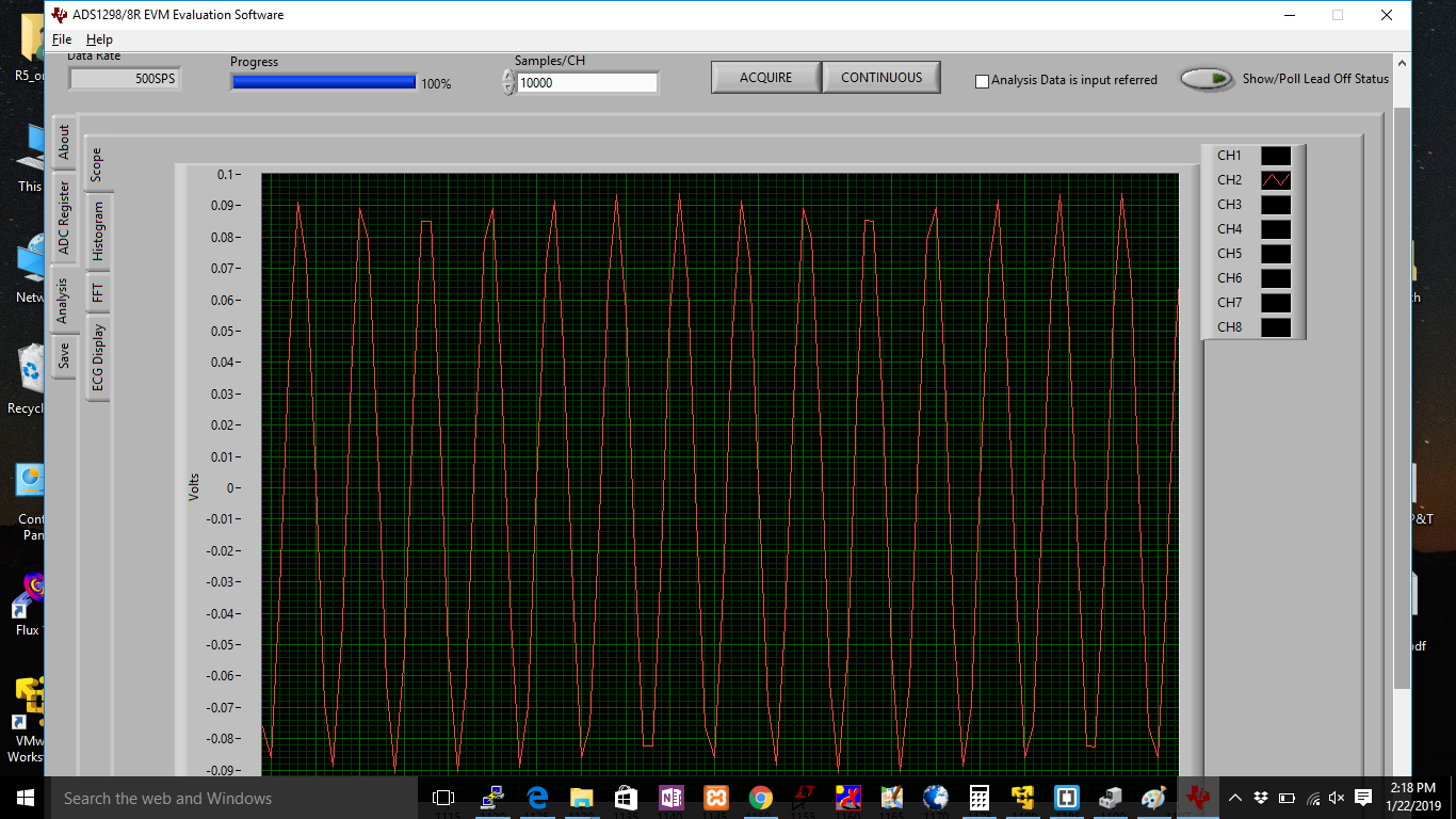
we were able to set up the EVM to receive the signals. we gave a signal of 100mVpp to channel 2(+ 50mV) of the device, it is receiving the signal and is being shown in the scope with a gain of 2. But when we change

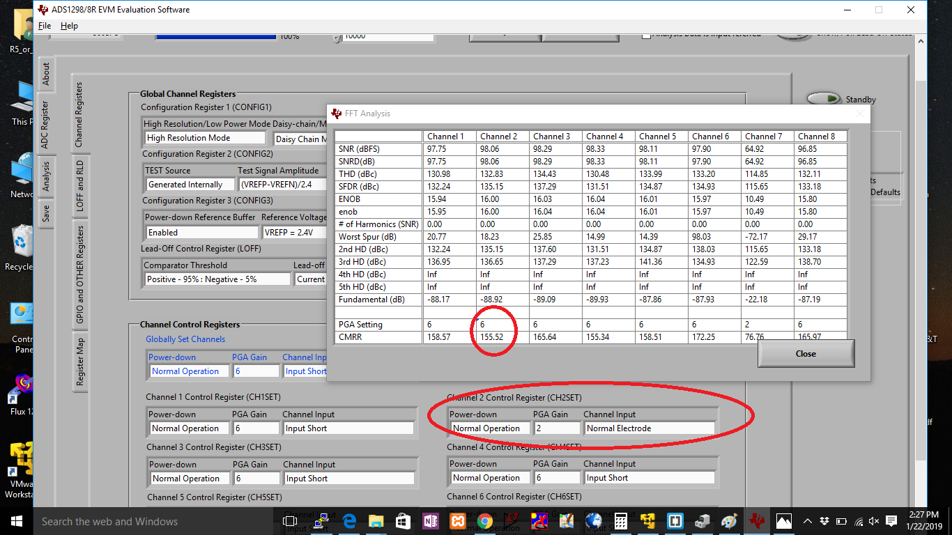
the programmable gain(PGA) setting from control registers, the result remains the same i.e. no change in the output signal in the scope.

Kindly clarify the issue, i.e. how to change the gain and view the update result on scope.

  • Hi Vasanth,

    Thanks for your post!

    Try unchecking "Analysis Data is input referred" in the scope analysis window.

    If you're measuring signals centered around GND, make sure that you're running the device using the bipolar power supply configuration.
  • Hi Alex,

    We were able to the gain for the  signal received but we had few more queries:

    1. Differential input of 100mVpp sinewave was given to channel 2(+ 50mV) of the device, but the output seen on scope is not pure sine even though we used 10000 samples/ch.

    2. FFT analysis shows magnitude plot, the gain showed here doesnt match the gain set from the GUI.for eg we set gain of 2 but magnitude plot gain is -10dB.One more thing also when opened FFT analysis window PGA gain setting showing is always 1 in fig.2.

    3. The EVM sampling rate maximum is 32ksps while acquiring the input signal data and processing it is taking  more time time like 40to 50 sec.Please clarify the delay issue.

  • Hi Vasanth,

    1. You need to change the sampling rate under the OSR in the registers tab. Changing the samples/ch just means that it performs the measurement for a longer time.

    2. Try increasing the sample rate as per questions 1. I'm assuming that there is a bug in the GUI that causes it to not update properly after changing the register settings.

    3. The device performs the measurement at 32ksps. This must then be read by the DSP and sent to the PC through the USB connection. Most of the delay is coming from the USB communication.
  • Hi Alex, 

    we are unable to find the OSR in Register tab if poss.Please tell briefly how to change sampling rate in register tab (if possible please send screenshot of it), so that my input sine wave should be clear picture in the GUI

  • Please explain point 2 in the above querry regarding FFT analysis related doubts . we attached the screenshot with highlighted ones.
  • Hi Vasanth,

    Sorry about that, I should not have used the acronym "OSR" which stands for "Oversampling Ratio". Might have been confusing.

    Try adjusting this ratio and let me know if it fixes both problems. This is important for the FFT as well, please see figure 52. of the datasheet for additional details.