This thread has been locked.
If you have a related question, please click the "Ask a related question" button in the top right corner. The newly created question will be automatically linked to this question.
Part Number: ADS1299EEG-PDK
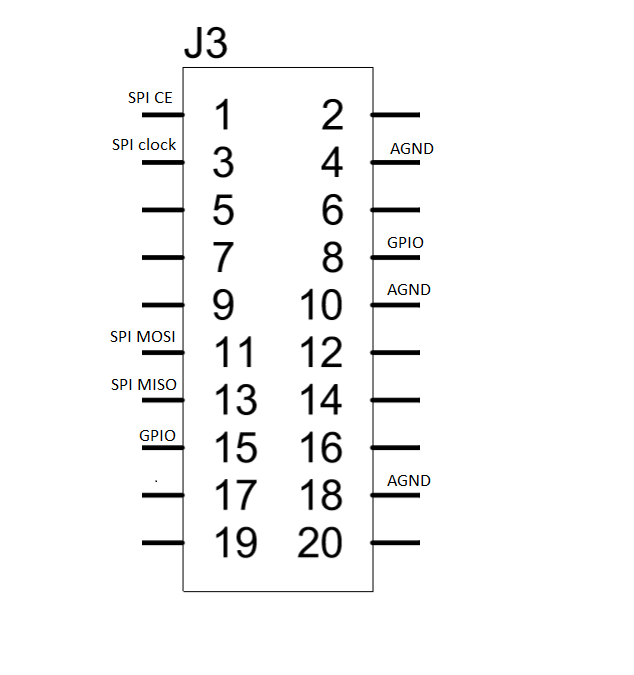
Hi TI, I am doing a project where I need to connect the ADS1299EEG-PDK card and transmit the collected data to a raspberry. Which ports do I need to power and which ports do I collect the data? Through the schematic, I discovered that the feed would be via j4 port and communication by j3, however I was afraid to burning board.
Could you please confirm if these links would work and inform me how I collect the ADS data?
Thank you!
Hi Joao,
If you look at Figure 62 in the ADS1299EEGFE-PDK users guide, you should see an explanation for the lack of 1.8V on TP9. Since you have 5.0V on TP7, you have to track back a little to figure out why you do not have -2.5V on TP6. Please refer to Figure 60 in the ADS1299EEGFE-PDK users guide and see what voltage is on TP4. TP4 is fed by a charge pump (U6) that takes the same 5V on TP7 and inverts it. That -5V then feeds a -2.5V regulator (U8) which should be the voltage found on TP6.