This thread has been locked.

If you have a related question, please click the "Ask a related question" button in the top right corner. The newly created question will be automatically linked to this question.

Compiler/ADS1299: ADS1299

Part Number: ADS1299

Tool/software: TI C/C++ Compiler

hello,

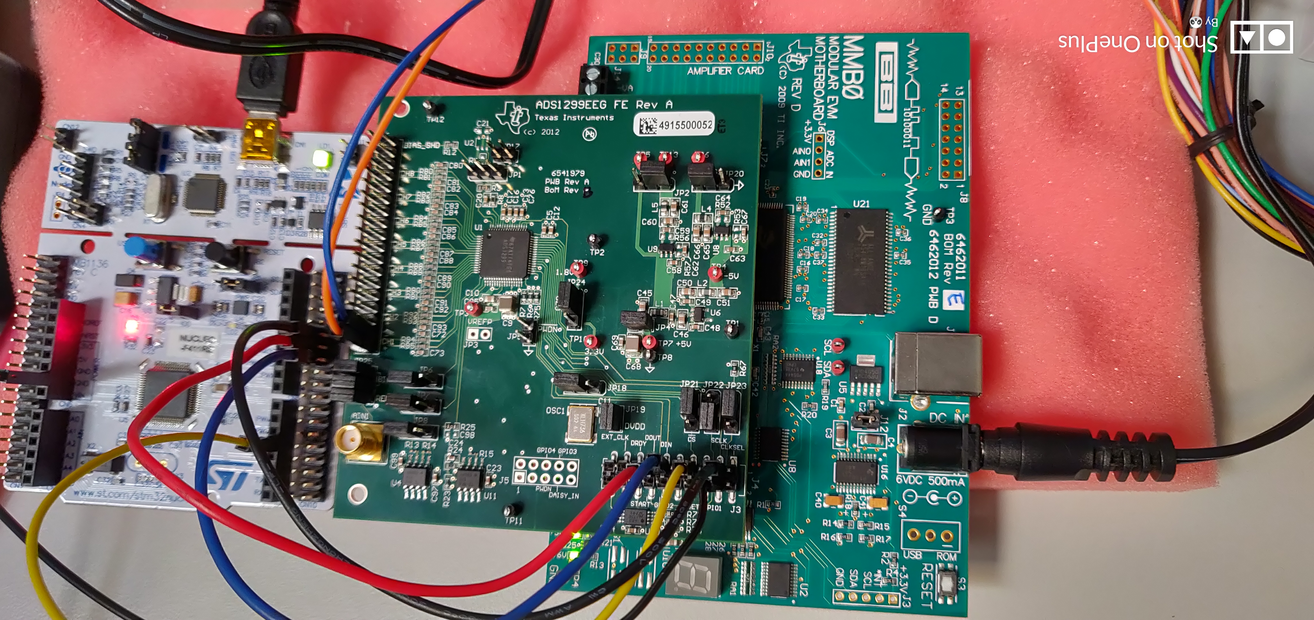
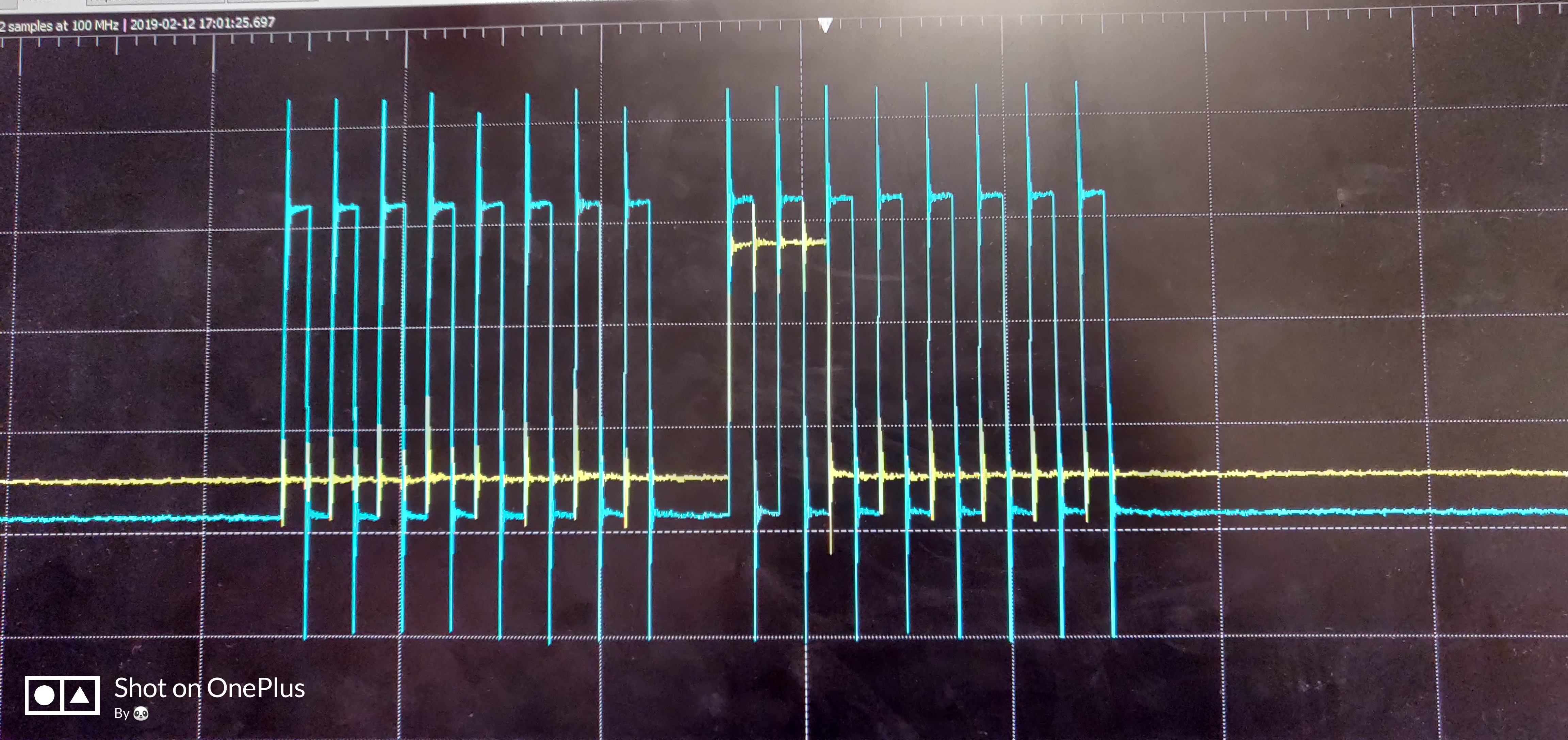
I am working with the ads1299 board since a while; I am trying to establish SPI communication, i went through the datasheet, but I am bit confused and not achieved to get proper output. Please help me with the right order of commands need to be followed for reading the continuous data from the board.

  • Hi Nikitha,

    Thanks for your post!

    1) Does the ID register read back correctly?
    2) Are you following the correct start-up sequence in section 10.1.2 and 11.1? After the power-on reset is complete, /DRDY should begin pulsing at the default data rate (assuming the START pin is pulled up). The /RESET pulse after tPOR is essential for bringing up the digital core in the correct state.
    3) Before trying to read the registers, are you sending the SDATAC command?
    4) Can you provide a schematic?
    5) What is the frequency and how many SCLK pulses are you sending to clock data out?
  • Hello,

    thank you for the reply.

    I wrote the following code for mbed compiler and it is quite understandable. 

    ____________________________________________________________

    #include "mbed.h"
    #define F 1000000 // 1 MHz


    SPI spi(PA_7, PA_6, PA_5); // mosi, miso, sclk
    DigitalOut cs(D4);

    int main() {

    long int data_in;

    // Setup the spi for 8 bit data, CPOL = 0, CPHA = 1 (mode 1) , with a 1MHz clock rate
    spi.format(8,1);
    spi.frequency(F); // SCLK_F = 1MHz

    cs = 1;
    wait_us(10);
    cs = 0;
    spi.write(0x06); // reset
    cs = 1;
    wait_us(10);


    while(1)
    {
    cs = 0;
    spi.write(0x11); // send SDATAC
    spi.write(0x25); // select channel 1
    spi.write(0x00);
    data_in = spi.write(0x00);
    printf("data in = %d\n", data_in);

    spi.write(0x10); // send RDATAC
    cs = 1;
    wait_us(10);
    }
    }

    _________________________________________________________________

    As output i get only zeros.

    Do I need to initialize any other signals such as DRDY and START?

    Is the communication flow correct?

    I'm powering the ADS board through MMB0 board without using the ADS software.

    Do I have to power it in some other ways?

    I post a picture below to show the HW setup.

  • 1) Does the ID register read back correctly?
    2) Are you following the correct start-up sequence in section 10.1.2 and 11.1? After the power-on reset is complete, /DRDY should begin pulsing at the default data rate (assuming the START pin is pulled up). The /RESET pulse after tPOR is essential for bringing up the digital core in the correct state. (To confirm, try probing the DRDY pin - you should see pulses at the default datarate)

    You should be fine powering through the MMB0, but to confirm you can probe the power pins to ensure that the device is receiving power.

    Your SPI SCLK may be too slow depending on how many channels you're polling and the output data rate. See this post for details: e2e.ti.com/.../2573727
  • Hello,
    I'm trying to interface the ADS1299eeg through SPI but I'm facing with a lot of problems. Actually I menaged to read various internal registers but the problem occurs 
    when I try to read the digital values of the analog inputs after conversion. In particular I can't obtain a correct behaviour as far the DRDY signal is concerned: the output is not as expected,
    consequently it looks that data are never ready and the read value after START is always the same. I'm following the flow explained in chapter 10.1.2 of the datasheet but I'm wondering if I have to follow a different procedure since I'm powering the ADS board through the MMO motherboard.
    In fact, as soon as I power it I verified that PWDN, RESET and START pins are already 'high' as the flow indicates. Could you make a summary of the right procedure and commands that I need to send in order to get a correct DRDY behaviour and to obtain the data in general? In case I want to power the ADS board in a different way, which is the best way to make the interconnections?


  •  The above picture the blue line refers to SCLK and yellow DOUT, the DRDY  is always high isn't toggling.

  • Hi Nikitha,

    For a summary of the right procedure and commands for correct DRDY behavior, please follow Figure 67. Initial Flow at Power-Up in the datasheet. 

    For powering the board without the MMB0, please see this thread: https://e2e.ti.com/support/data-converters/f/73/p/105352/379169#379169

    You have a high over/undershoot on your SCLK. Check to make sure that this over/undershoot is within the guidelines of the datasheet for digital communication. If the over/undershoot is out of specification then the device may not read the pulses properly. 

    Additionally, check to make sure that the pin monitoring DRDY is not reserved/held in a constant high state by the MCU.