This thread has been locked.

If you have a related question, please click the "Ask a related question" button in the top right corner. The newly created question will be automatically linked to this question.

ADS127L01: THS4551

Part Number: ADS127L01

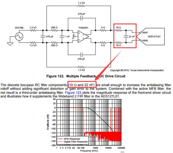
Following the data sheet of ADS127L01(Figure below), We designed the MFB filter. The reference design is 10R and 22nF, so ithe cut-off frequency is 1/(2 * pi * R * C) = 723798.5Hz. Since our sampling frequency is 128K, we want to design a cutoff frequency at 100kHz following your recommendation. So, we change parameter to 160R and 10nF, which would generate a cutoff frequency at 1/(2 * pi * R * C) =100kHz

However, the test result is not as designed. The input signal amplitude is 0.224V, The input frequency and output signal’s amplitude can be seen at next table, the cutoff frequency is acutally at 10kHz, not 100kHz.

10KHz - 0.222V

20KHz - 0.209V

30KHz - 0.188V

40KHz - 0.180V

50KHz - 0.164V

60KHz - 0.149V

70KHz - 0.136V

80KHz - 0.124V

90KHz - 0.114V

100KHz - 0.105V
110KHz - 0.098V

120KHz - 0.091V


How select the resistance and capacitance of this low-pass RC filter to achieve 100kHz cutoff frequency?

  • Hello,

    The 10ohm/22nF RC is tuned to drive the input sampling capacitor of the ADS127L01. You should not change these values, as they are optimized for the ADS127L01.

    I assume you are selecting the OSR=128 when using a master clock of 16.384MHz to achieve an output data rate of 128ksps. In this case, the modulator frequency does not change, and the filter in Figure 122 of the data sheet is still a recommended design. With 128ksps using the Wideband 2 Filter, your pass band will be 51.2kHz, limited by the internal digital filter. The modulator aliasing will still occur at 16.384MHz, and the filter design in Figure 122 will provide -100dB of attenuation at this frequency, effectively eliminating unwanted aliasing at this frequency.

    Regards,
    Keith N.
    Precision ADC Applications