This thread has been locked.

If you have a related question, please click the "Ask a related question" button in the top right corner. The newly created question will be automatically linked to this question.

ADS127L01: Timing requirement 2

Part Number: ADS127L01

Ryan-san,

Our customer has still observed no /DRDY ramp down phenomena even send START data more than 4x CLK < tw(STL).

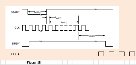
In previous thread, you commented that SCLK input is not allowed before /DRDY ramping down, to secure correct data loading into shift register, like following drowning.

Q3-1: Can we expect the reason of this no /DRDY ramp down is caused by SCLK clock input before /DRDY ramp down ?

If input SCLK during this time frame, will it create not only breaking shift register data but also keeping /DRY pin H even after tsu(ST) + td(FILT) + td(NDR)?


Regards,

Mochizuki

  • Hi Mochi,

    An active SCLK input before the falling edge of /DRDY will not capture correct data, but this should not effect operation of /DRDY line. The /DRDY line should still operate properly in this case even though you will have corrupted data.

    In order for the START pin to function properly, it must be pulled low for at least 4 CLK periods or longer. If the rising edge of START does not meet the setup and hold times relative to the CLK signal, then you may not START until the following CLK period, but the device will still START properly. The importance of the setup and hold times is to ensure multiple ADC's are all synchronized to the same CLK edge, but with one part, this is not as important.

    Once the part is powered up with a valid clock signal on the CLK pin (100kHz to 17.6MHz for HR mode, 100kHz to 8.8MHz for LP mode), the /DRDY line should toggle low at the output data rate. In HR mode, OSR=128, and 16.384MHz CLK, the /DRDY pin should toggle at the output data rate of 128ksps.

    Please ask the customer to confirm that the START and RESET pins are pulled HIGH to DVDD (3.3V) and verify the frequency of the CLK signal on pin 24 of the device. Also, the LVDD pin should measure 1.8V, and the Analog supply AVDD should be 3V. If possible, please include the schematic in case there is an error in the connections to the device.

    If the START or RESET pins use a pull-up resistor, try reducing this to 1k-10k. We recommend 100k to minimize power consumption, but if the CLK signal has fast edges and is coupling into either of these pins, it could cause the device to continually RESET or restart, which would result in the /DRDY line stuck on HIGH.

    Regards,
    Keith N.
    Precision ADC Applications
  • Hi Mochi,

    Since there have not been any updates to this thread for several days, I am going to go ahead and close this out. If there are follow-up questions, please feel free to start a new e2e thread.

    Regards,
    Keith