This thread has been locked.

If you have a related question, please click the "Ask a related question" button in the top right corner. The newly created question will be automatically linked to this question.

ADS125H02: suggestion for a wider front end ADC

Part Number: ADS125H02
Other Parts Discussed in Thread: MUX507

Hello team,

in one of my applications I'm planning to gather differential and single ended signals towards the ADS125H02.

Since the signals have a dynamic of about +/- 20V I'm also looking for MUXs with a Dual Supply Range of +/- 22V but I've asked to the right Section of the forum this matter.

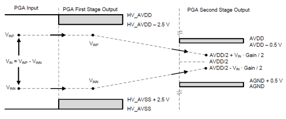
As you can see, in order to adapt the voltage levels to the ADC it is still necessary to add a precision divider. Unfortunately, the ADC has a theoretical front-end of +/- 20V only, which becomes about +/- 16V, considering all the internal thresholds, see below:

What do you think of this architecture? It might work? Now we have planned (x2) MUX507 but they’re a bit on the edge of negative voltage.

Are there any ADCs with a more extensive front end ? Do you have any other idea?

Please any thoughts is welcome.

Thank you in advance for your support.

Best regards,

Adrian

  • Hi guys,

    could you please give any input here?

    Thank you in advance!
    Best regards,
    Adrian
  • Hi Adrian,

    Sorry for the delayed response.

    If you're able to to provide an external 5V reference, and use +/- 15 or +/- 18V HV supplies, then you should be able to measure the +/- 22V signal directly...

    In the case of +/- 18V HV supplies, the first stage PGA will be able  to measure +/- 31 V (36V supply span - 5V headroom). The output of the second stage PGA will be 31V * 0.125 = 3.875V, which is  okay as long as you supply a larger reference voltage.

  • Hi Chris,

    I have no problem feeding the ADC with +/- 18V and the ADC's Vref is already at 5V but I don't understand how the first stage can even measure +/- 31V, maybe you mean Vdiff = VINP-VINN?

    Unfortunately I find myself in this situation VINP = -VINN = + / - 20V ie Vdiff = + / - 40V. Using the attached spreadsheet for the ADS125H02, we find VINP = VINN = + / - 15.5V as a limit, at least that's what I understood.
    Please correct me if I'm wrong.

    Do we have plans to work on ADCs with more extensive front-ends than ADS125H02 ?

    Thank you in advance for the support.
    Best regards,
    Adrian
  • Hi Adrian,

    Correct, I was referring to a differential voltage. +/- 31 V is the maximum differential voltage (VINP = +15.5, VINN = -15.5) that can be applied directly to the ADS125H02.

    Let me take your request for future device plans offline. Please be on the look out for a separate email.