This thread has been locked.

If you have a related question, please click the "Ask a related question" button in the top right corner. The newly created question will be automatically linked to this question.

ADS7953EVM-PDK: ADS7953EVM-PDK

Part Number: ADS7953EVM-PDK
Other Parts Discussed in Thread: ADS7953, ADS7951

I am interfacing the above EVM board with a Arduino mega board. Irrespective of the channel selection I am able to measure only the channel 0. No measurement is possible from any other channels.

At Power up I write this data for configuring in the manual mode : 0x18  0xCF 

The Adc measurement for channel -0 is coming out good and the reference used is 2.5 V.

SPI Setup :  SPI.beginTransaction(SPISettings(1000000, MSBFIRST, SPI_MODE1));

Any help is appreciated.

Regards

Raj

  • Hello,

    Would you provide a scope shot of the digital communications, including SDI, SCLK, SDO, and CS. This allows for visual inspection of the digital communications, and be compared to what is expect from the processor vs what it is doing in reality. please include 3 frames.

    Also, for debugging I would suggest using known DC values at the inputs of the ADC, for example ch1 = 1v, ch2 = 2V, and so on, to know what to expect as the measured output.

    What mode are you running the device in? during debugging I would suggest manual, to confirm correct communication. From there the device can be configured to other modes

    Regards

    Cynthia

  • Hello 

    Thank you for the quick response.

    Currently I am able to get the correct ADC count from the device for the following known values.

    2.5 V  - 4096

    0 V    - 0 

    1.85  -2950 

    The mode configured is currently Manual /No Power down/Channel/GPIO configured as output /Range : 2. 5 V

    The issue is I am able to get the adc count only for Channel 0. When I put the same code in the for loop for all the channels the channel number I get is still 0 and the channel 0 ADC value.

    I will try to provide you the snapshot soon.

    Thanks for your help.

    Regards

    Raj

  • Hello,

    In manual mode, you have to select what channel to sample next. If you continuously send the same command, then the same channel will continuous be sampled.

    Based on the table below, the bit DI010 to 07 need to change to sample the different channels. Please do so, and let me know if this fixes the issue.

    Also, if you are using commands 0x18h, 0xCF, bit DI04 is low, which means the device is outputting the channel that the output data corresponds to. During all your samples, the first four bits should have always been the same well.

    Once correct configuration is achieved, you might consider using a different mode. this device supports Auto scanning modes which will sample a predetermined sequence of channels at every frame. This differs from manual where each frame the user selects the next channel to sample.

    Regards

    Cynthia

  • Hello,

    This is the simple code where I am trying to read successive channel :

    The code is programmed in an Arduino-Uno and it runs continuously in an indefinite loop:

    Serial.println("Chan-0");
    digitalWrite(ADC_CS, LOW);
    //Send in command byte
    result[0]=SPI.transfer(0x18);
    result[1] =SPI.transfer(0x4F);
    //Disable device
    digitalWrite(ADC_CS, HIGH);
    Serial.println(result[0],HEX);
    Serial.println(result[1],HEX);

    --------------------------

    The serial output varies 

    Chan-0
    B

    96

    0

    --sorry for the larger image size. I will try to get you a 3 frame sequence.  

    The confusion is why I am getting a Channel number as 9 instead of 0 . The code above is the one that is running in the Micro. I did not change any channel number. 

    Regards

    Joseph

  • Hello,

    In manual, if you send the same frame, continuously, the same channel will continue to be sampled. It will not change. DI 10 to 7 need to select the channel

    Example, for channel 2 it would be 0010, thus the whole command would be 0001 1001 0100 1111 = x49h; x4Fh

    When you provide the three frames, please let me know which line is which signal, right now I am assuming the pink line is SDI, and the blue line is SDO

    the first four bits of the SDO are the channel that the conversion result corresponds to, as you have it configured, which looks to be channel 0.

    Regards

    Cynthia

  • Hello,

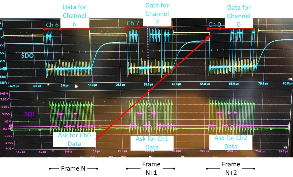
    I am still having issues in reading the values from the ADS7953.  I have connected a 1.8V DC to channel -3 and the value received from SPI is 0x0F7.

    Please see the image attached.

    Reference  : Pink - SDI /Green - CLK /Blue-SDO . The concern is the ADC count does not correspond to the correct dc value applied to the channe.

    Command Info : CH0- 0x1840 CH1-0x18C0 ,CH-2 -0x1940 CH-3 0x19C0 ...CH-7  0x1BC0 

  • What are your power supplies?

    To what voltage is the SDO pulled high to? In the oscilloscope shot, the voltages on the side are cut off. the signal seems to be at different voltages from when SDO is being driven to when it is not. What size resistor are you using and to what voltage is it connected to? SDO should be pulled no higher than the VA supply.

    Currently you are setting the input range as 2xVref = 2 x 2.5V = 5V

    I cannot verify if Channel 3 Data is correct for 1.8V input, as it is not available in the scope shot you provided. The data from the scope shot that show an SDO value of 0x0F7h, is actually for channel 7, not channel 3 in Frame N+1

    The device looks as it is working correctly though, it seems you are interpreting the results wrong.

    Take the diagram below found in the datasheet. When you program the device to sample a channel, the data for that channel will not be available until 2 frames after the initial one. This is why I asked for three frames.

    The first four bits of the SDO will state the channel the data corresponds to, this is helpful to ensure there is no mix up.

    If you apply this to your scope shot, it is this:

    Also, You do not need to continue to program bit 11 as high if you do not want to change the configuration of the device, for example the reference/range. The latest configuration will be used until changed. Also Bit 11 does not need to be set high to change the channel to be sampled.

    Regards

    Cynthia

  • Hi Cynthia,

    Thank you for the detailed clarification. This has resolved my issue.

    Additional Clarification and suggestion required :

    I need to use the GPIO pins on the ADS7951 Chip. The GPIO-0/1 has to be configured as an output port and GPIO-2/3 has to be configured as an input. At Power on I program the GPIO Register with the below value.

    0x4003 . 

    I can command the output GPIO with the 2 bits of the SDI command. In the manual mode how to read the status of the Input pins. I am also looking for the Channel numbers to be output on the higher bits ( D15,D14,D13,D12) . 

    Is this possible in the manual Mode ?

    Regards

    Joseph

    I mad the 

  • I am glad that helped,

    You can only show either the channel count or the GPIO values at a time, in other words, one SDO cycle can either show GPIO values or channel.

    You can alternate with every SDI command and change how to use the SDO bits: D15,D14,D13,D12, if that works for you.

    In manual mode, the GPIO functionality is available. But remember to follow the table below. The command you shared is incorrect.

    Glad you are on your way, the datasheet will be of great help