This thread has been locked.

If you have a related question, please click the "Ask a related question" button in the top right corner. The newly created question will be automatically linked to this question.

DAC38RF82EVM: Distorted signal output

Part Number: DAC38RF82EVM
Other Parts Discussed in Thread: LMK04828, DAC38RF82

Hello.
Setup: I have a DAC38RF82EVM , and I'm attempting to use it with a Xilinx VC707 and TI's interposer board - TSW14J10.
Problem: I'm unable to see a sine wave generated by HSDCP on my scope without NCO and mixer.

On the other hand:

  • I am able to output clear sine using the "Constant input" checkbox with mixer and NCO.
  • I created a CSV file with a constant value, load it with "Load external pattern file" and send, with mixer and NCO enabled, I also see a clear sine.

Can someone help please?

Details:

I'm attempting to use it according to the powerpoint presentation from :

I don't connect a 10 Mhz clock to J4, so I don't expect D3 to ever light up.
D4 remains off, even though it should go on, indicating LMK VCO1 locked.

However, the DAC's PLL does lock.
In accordance with the interposer manual, section 6, I configured the LMK to output 384 Mhz DCLKOUT0 - JESD reference clock and 192 Mhz to DCLKOUT12 - JESD CoreClock.

It seems that the FPGA is "good" - VC707 Leds 0,4 are on ( DAC SYNC indicator, DAC JESD mode enabled ), and leds 5,6,7 are blinking.
Also D8 - JESD SYNC on the EVM is on.

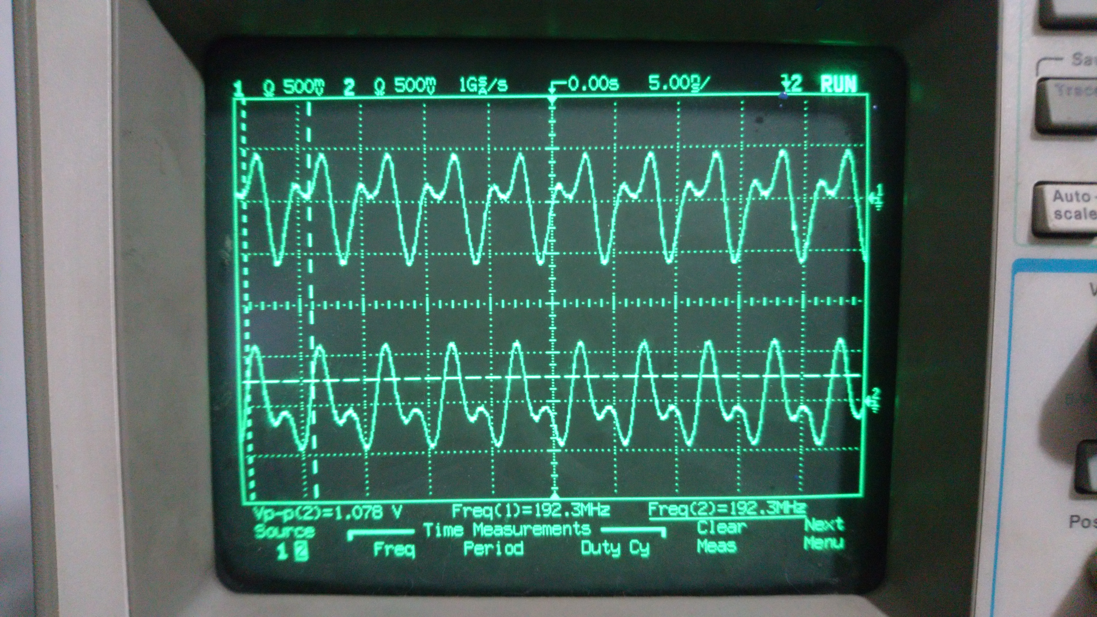
When I configure HSDCP to generate a 200 Mhz, I see on the scope a sinewave signal that looks good, only it's 192 Mhz, not 200.
The lower I go from 200, the more distorted 192 Mhz wave I get.


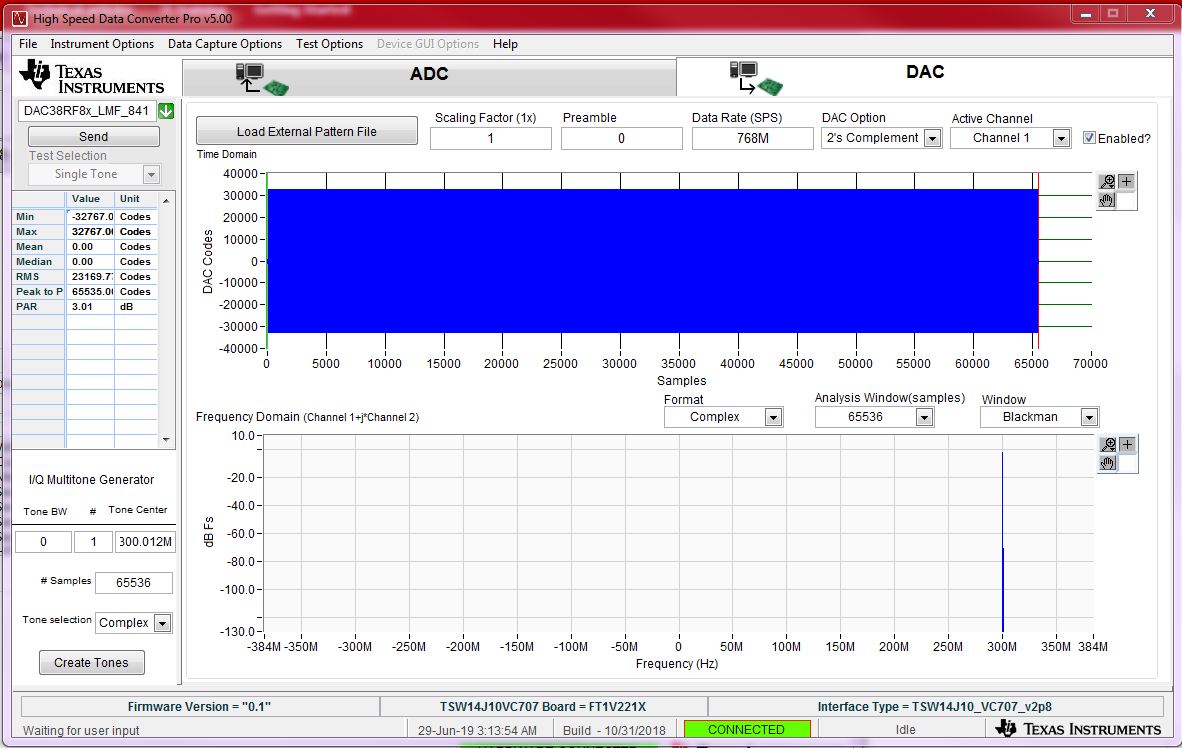
I configured DAC B to use constant input with NCO at 48 Mhz and mixer so we can easily see the signal on the scope and compare.

The following is a snapshot of me trying a 48Mhz sine on channel A, and a 48 Mhz sine generated by NCO and mixer on channel B.

The following is me trying to generate a 150 Mhz sine on DAC A, and DAC B generated 48 Mhz as above:

  • Hi Cohen,

    1) Just to make sure you have the clocks set up correctly, I have modified the ppt (slide 7) with the right LMK04828 clock divider settings for VC707 for you to review

    2) Can you share screenshot of hsdcpro?

    3) Can you connect the DAC output to a spectrum analyzer so we can see all the frequency content?

    Thanks,

    Eben.

    DAC38RF82_6144M_PLL_3072M_ref_841_tsw14j10.pptx

  • 1) I followed the presentation you sent, and still get very similar results.
    As I mentioned, I configured the LMK exactly as you wrote - divide by 8 to get 384 Mhz for DCLKOUT0  and divide by 16 to get 192 Mhz for DCLKOUT12.
    I also verified these are the correct frequency by connecting the scope to J24 and enabling DCLKOUT4.

    2)  Here's a snapshot of HSDCP:

    Here's a picture of what I see on the scope (Channel 1 is connected to J6 - IOUTA , Channel 2 is J2 - IOUTB-SE ):


    I get something very similar if I change both "Tone selection" and "Format" to real.

    3) I don't have a spectrum analyzer available at the moment.

    As you can see I have HSDCP version 5.00.
    Dll version 0.1, Firmware version 0.1.

    My DAC software is version 3.0, build date 02 february 2019.

    The board is marked "DAC38RF82 EVM" -  PCB REV F.

  • Hi Eyal,

    Eben is currently out on leave so I will try to help on this topic.

    My understanding of the current problem is the following:

    1. output higher frequencies tones (even with test tones) is limited to 192MHz

    2. the 192MHz has distortions in the time domain.

    Please confirm if my understanding is correct.

    I see that you have set HSDC PRO to output 300MHz, for instance, with data rate at 768MSPS. There are multiple interpolation stages happening in the DAC upconversion circuits. The initial interpolation by 2 circuit has roll-off bandwidht of roughly 80% of the data rate. With 768MSPS, the maximum I/Q complex bandwidth is 384MSPS. Since the DAC38RF82 is a real signal upconversion, we will have only 384MSPS of bandwidth. With 80% roll-off, you get 307.2MHz as the maximum. You are close to the edge of the roll-off, and it is possible some images during the interpolation process may leak into the main Nyquist zone. This may explain that the waveform changes as you reduce the output frequency.

    I recommend to observe the output in a spectrum analyzer with sufficient RF range to observe the output. The current time domain plot may have bandwidth limitations from your scope. The output of 192MHz may be combinations of the output and also its associated aliasing components, hence the additional distortion. 

    Please go through the following app notes on the potential problem introduced by the images from the interpolation stages and also the associated DAC output images

    -Kang

  • Hi Eyal,

    Eben is currently out on leave so I will try to help on this topic.

    My understanding of the current problem is the following:

    1. output higher frequencies tones (even with test tones) is limited to 192MHz

    2. the 192MHz has distortions in the time domain.

    Please confirm if my understanding is correct.

    I see that you have set HSDC PRO to output 300MHz, for instance, with data rate at 768MSPS. There are multiple interpolation stages happening in the DAC upconversion circuits. The initial interpolation by 2 circuit has roll-off bandwidht of roughly 80% of the data rate. With 768MSPS, the maximum I/Q complex bandwidth is 384MSPS. Since the DAC38RF82 is a real signal upconversion, we will have only 384MSPS of bandwidth. With 80% roll-off, you get 307.2MHz as the maximum. You are close to the edge of the roll-off, and it is possible some images during the interpolation process may leak into the main Nyquist zone. This may explain that the waveform changes as you reduce the output frequency.

    I recommend to observe the output in a spectrum analyzer with sufficient RF range to observe the output. The current time domain plot may have bandwidth limitations from your scope. The output of 192MHz may be combinations of the output and also its associated aliasing components, hence the additional distortion. 

    Please go through the following app notes on the potential problem introduced by the images from the interpolation stages and also the associated DAC output images

    http://www.ti.com/lit/an/slaa523a/slaa523a.pdf

    -Kang