This thread has been locked.

If you have a related question, please click the "Ask a related question" button in the top right corner. The newly created question will be automatically linked to this question.

ADS1299: Bias electrode and line noise rejection

Part Number: ADS1299

Hi all, 

I've built an EEG device based on an ADS1299. I'm using it to record EOG's now, working with CH1 and CH2 in differential mode, one for the horizontal and the other for vertical direction. I'm also using the Bias electrode, which I connect to the patient's ear lobe.

I have updated the bias filter to have a cutoff frequency below 50 Hz, instead of the 150 Hz recommended on the datasheet.

I am experiencing though some (random) wandering baseline and 50 Hz noise superimposed on the EOG signal. I need to remove this to get a proper measurement and due to the low frequencies I'm working with, digital filtering ends up adding distortion too.

I would like to confirm that the settings I'm using are correct:

  • CONFIG3 = EEh (this is reference buffer powered up, internal biasref signal, bias buffer & sense enabled and bias connected).
  • BIASSENSP = 03h (I'm using CH1 and CH2 here)
  • BIASSENSN = 03h

Is there any configuration wrong or that I'm missing?

Thank you!

  • Hi Florencia,

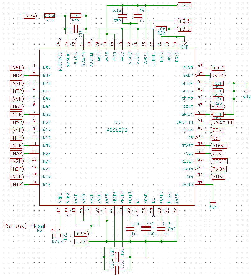
    Can you post a schematic? 

  • Yes, sure, here it is.

  • Hi Florencia,

    Are the electrodes directly connected at the input nets or do you have some kind of passive input filter? 

    What is the purpose of R18/R3?

    Why was the cutoff frequency of the bias filter set to 50Hz? What values are you using? The schematic shows a cutoff of ~159Hz. 

    Try increasing the cutoff frequency of the bias filter. For the bias drive to work properly, it needs to be able to pass the sources of noise back onto the body, typically 50/60Hz depending on grid frequency. This noise will then be canceled once it reaches the inputs of the PGA.  

  • Hi Alex,

    1) Yes, the electrodes have an input filter as the one shown in the ADS1299 kit application note (page 51, input schematics):

    2) R18/R3 are also taken from that design.

    3) Sorry, I said it the other way round. I've set the bias filter first with the recommended values but that had a cutoff frequency of 40Hz, so I updated the R and C values to the ones indicated in the schematic, which moved the cutoff frequency to ~159Hz.

    Even with these updates I still get the baseline drift in both channels (it's like a common mode noise there) and 50Hz mounted on my signal. Shouldn't this be minimal if I'm measuring in diff mode and using bias? Thanks!

  • Hi Florencia,

    Ah I see, I just wasn't used to seeing R18/R3 in that location. 

    Can you provide pictures of the waveforms you're seeing? 

    DC baseline variation is typically due to variations in impedance between the electrode cables and contact between electrode and patient. In the presence of a current, voltage forms and the baseline wanders. This is typically handled in post processing and making sure that the electrodes have a good connection. Using sandpaper on the skin, wet electrodes, making sure there is minimal movement while taking the measurement all have an effect.  

    Instead of trying to derive the bias voltage from the input pins, try just using mid-supply. Probing the bias output to see what voltage is present would be valuable to know as well. 

    This thread may help: https://e2e.ti.com/support/data-converters/f/73/t/813144