This thread has been locked.

If you have a related question, please click the "Ask a related question" button in the top right corner. The newly created question will be automatically linked to this question.

DAC38RF82: Fusefarm Autoload sequence is not done of 0x7F register(DAC38RF82)

Part Number: DAC38RF82

Hi,there

Our aim is  to see any signal on CLKTX+/- pins (a divided DAC CLK).

We are following the sequence in figure 141,Page126 of DAC38RF82 DATASHEET;

The sequence is as below:

1.Pull Txenable low;

2. Pull TRSTB pin of the JTAG port low

3.Toggle RESETB pin low then high (pulse duration =1ms)

4.We use the DACCLKSE input (120MHz / 1Vpp sine wave which is detected ok), bypassing the DAC PLL

5.Write the following data to the following registers:

address             |            data 

0x01                  |           0x1880

0x40B(page4)   |           0x0020

0x40C(page4)   |           0x2702

0x431                |           0x3000

0x43B               |           0x0000

Our problem : Every read from 0x7F returns a value 0x0009; It means Fusefarm Autoload sequence is not done of 0x7F register

I don't what's wrong with my design,Please help me out of confusion


best regards 


  • We are looking into your question and will get back to you asap

    Thanks

    Yusuf

  • hello,Jim

           I have solved my problem,But I have some questions to ask you

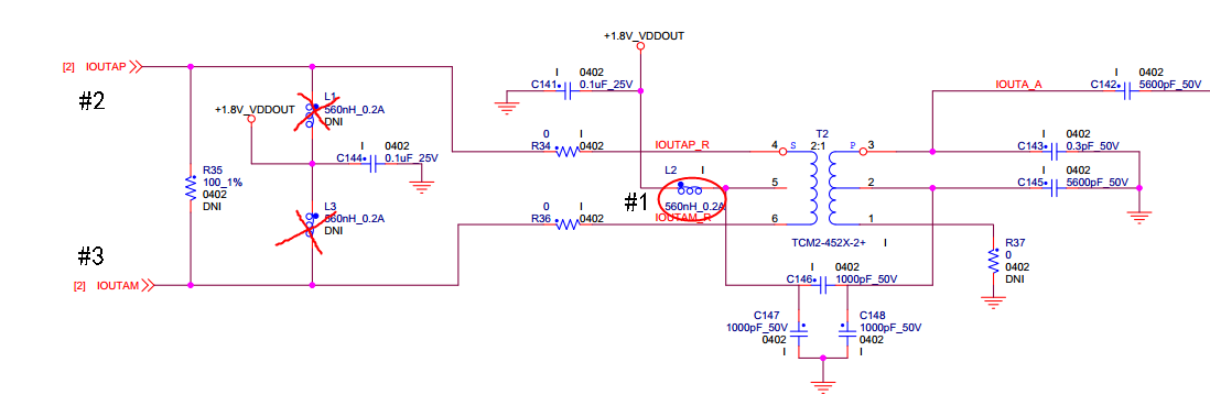
              I find some problem with my hardware,  The schematic diagram is shown below:

    1. IOUTAP(#2) and IOUTAM(#3) are not get the Voltage  1.8V_VDDOUT for the Welding problem of #1  inductor.

    2. We rewelded the  #1 inductor,Fusefarm Autoload sequence is set done of 0x7F register.

    my question: what is the reason of  IOUTAP(#2) and IOUTAM(#3) affect the Fusefarm Autoload sequence.

  • User,

    After a reset pulse is issued, the DAC will use the diff clk input by default and the fusefarm will not load. After the reset has been issued, Wwrite a "1" to bit 13 of Misc address 0x31 to set the DAC to use the single-ended input clock. Next write a "1" to bit 11 of address 0x00 to do a fuse farm load. After several ms, read register 0x7F and see what you get. Also make sure the reset pulse is 1ms like mentioned by verify this with an oscilliscope.

    Regards,

    Jim

  • hello,Jim

           I have solved my problem,But I have some questions to ask you I find some problem with my hardware,

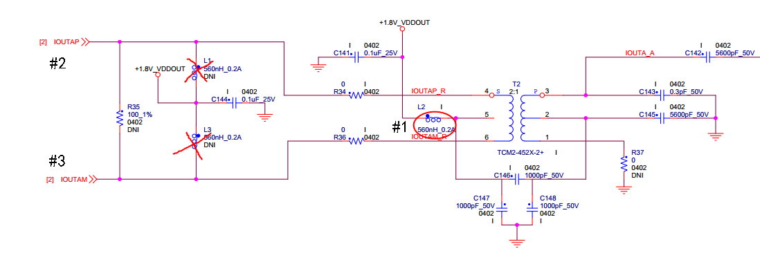
           The schematic diagram is shown below:

          1. IOUTAP(#2) and IOUTAM(#3) are not get the Voltage 1.8V_VDDOUT for the Welding problem of #1 inductor.

          2. We rewelded the #1 inductor,Fusefarm Autoload sequence is set done of 0x7F register.


         my question: what is the reason of IOUTAP(#2) and IOUTAM(#3) will affect the Fusefarm Autoload sequence?

                             Could  you explain the reason  for me ?


    Best ragards

  • My only guess is the +1.8V_VDDOUT supply is used by the device to do the Fusefarm autoload or you may have had an issue with another +1.8V supply. This probably had nothing to do with the IOUT signals but one of the DAC power supplies.

    Regards,

    Jim