This thread has been locked.

If you have a related question, please click the "Ask a related question" button in the top right corner. The newly created question will be automatically linked to this question.

ADS1299: EEG ADS1299

Part Number: ADS1299


      Hello, please help me confirm whether to add instrument amplifier and operational amplifier before feeding the collected electrode eeg signal into the AD1299 chip?

Or can I do a simple RC filter and then directly connect to AD1299?

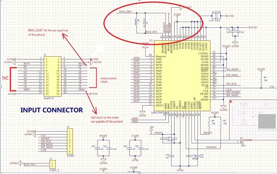
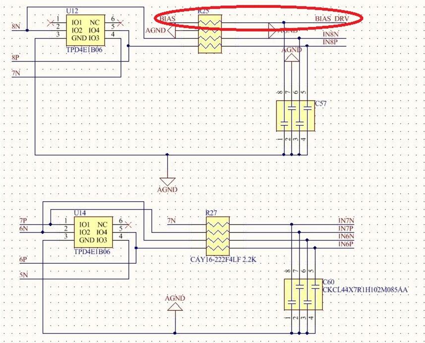
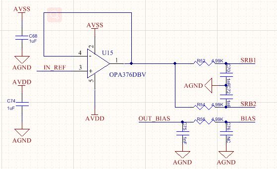
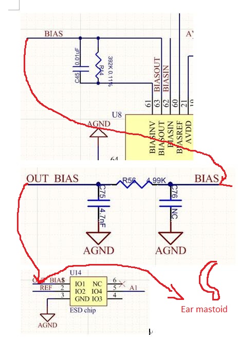
Q2: Is the BIAS schematic partially correct, with BIAS directly connected to the BIAS electrode?

  • Hi, 

    We typically recommend not adding a pre-amplifier as it will increase the amount of noise introduced into the signal. If your signal magnitude is so small that you're considering this, reducing the voltage magnitude of the reference would be a better approach. This thread may help: https://e2e.ti.com/support/data-converters/f/73/t/415841

    We do recommend having an RC filter before the inputs so that high frequency signals do not alias back into the sample band. 

    The bias schematic looks correct to me. 

  •    

    thank you very much for your reply, I have one more question. I'd like you to take a look at it.

    Q1:As shown in the figure, the original signal with electrodes is drifting, and the baseline is changing constantly. If so, will it lead to full deviation?

    Q2: When we test the signal, we have an image, there is a very obvious burr signal, excuse me, what is the reason?

       We have a few kinds of conjecture: 1, environmental electromagnetism interference 2, hardware circuit interference does not know is what reason?Could you take a look at it for me?


     this is the jump data for a single channel.

  • Hi,

    Are you using the RLD electrode? If so, can you confirm that it is working correctly?

    Can you share a schematic that shows your input structure? 

    If you are not using the RLD electrode, then this post will help: https://e2e.ti.com/support/data-converters/f/73/t/799662

  •         hi,Thank you very much for your reply!

    I'm sure I connected the right leg drive circuit(bias electrode).But could you please help me confirm the schematic diagram again?

    What circuit should be added to the right leg circuit?

    I am redesigning the circuit board. Can you provide a simplified demo schematic?It's not kit board. 

        good luck!

  • Hi,

    Can you confirm that the RLD electrode is outputting the intended voltage?

    Please see the ADS1299EEGFE-PDK user's guide for an example schematic.

  •        Hi,

             outputting the intended voltage:  What should the voltage be?How do you measure it? I didn't measure it before.

    I would like to ask if my schematic diagram is correct, and I need your exact answer, because I am designing PCB board.

            thanks!!

  • Hi,

    I apologize for saying RLD in my last post, it performs the same function but has a different name for ECG. 

    What did you configure it to be? Are you buffering mid supply or using the inputs to derive the BIAS? 

    You can simply use an oscilloscope to measure at the BIAS_DRV node or at the end of the BIAS electrode. 

    The schematic looks fine at this point, but you need RC filters on the inputs and I would recommend addressing the baseline issue before moving forward with the layout. If you do not want to use the BIAS electrode you can use the configuration as shown in the post I linked earlier. 

  •   Hi, "using the inputs to derive the BIAS?"  that's exactly the kind of Bias I think is using the inputs to derive the Bias.Is that so?

          The direction of the signal is shown below, right?

    buffering mid supply  AND using the inputs to derive the BIAS :What are the advantages and disadvantages of these two schemes?

    Q2:Do you think the baseline problem is caused by bias elec?

    Q3:I also have a burr phenomenon, as shown in the figure above, can you help me locate the problem point?

  • Hi,

    For question 1, how did you configure the device? Please see the register map section of the datasheet for reference. 

    Q2: Yes, I recommend using mid-supply to debug for now instead of deriving from the electrodes. More than likely your circuit is unstable right now and that's what is causing the drift. 

    Q3: This is probably data corruption. Please see the code to volts post in the FAQ and ensure that your MCU is capable of collecting the data fast enough before a new sample is loaded. 

  •    hi,

      1、Below is my configuration table

    2、BIAS_SHD BIAS_DRV BIAS_ELEC what's the relationship between them?


    • You mean you want me to connect BIAS ELEC to 1-2 of JP6 and BIAS ELEC connected to the auricular mastoid process?

      Can you give me a complete schematic?Because I refer to the "EEG frond-end Performance Demonstration Kit", it has too much free configuration, I am a little confused,especially with bias, it's a bit of a mess.

    • Can you send me your personal email?I'll send you the complete schematic and check it for me
    • 3、We tested it, it's not data corruption, it's the burr that happens when someone walks by while we're wearing the electrodes,Is there any way to avoid this?

            good luck!

  • I'll send you a note to forward the schematic over. 

  • Hello, could you please help me take a look at the problems mentioned above?Thank you very much!

  • Hi,

    I sent an email to the address registered with your account to view a full schematic. Did you not receive the email? 

  • Hi,

        I have some questions. I have sent them to your email. Could you please check them for me?

    thanks!!