This thread has been locked.

If you have a related question, please click the "Ask a related question" button in the top right corner. The newly created question will be automatically linked to this question.

ADS1298R: Obtaining Waveforms only one of the channels.

Part Number: ADS1298R

Hello, 

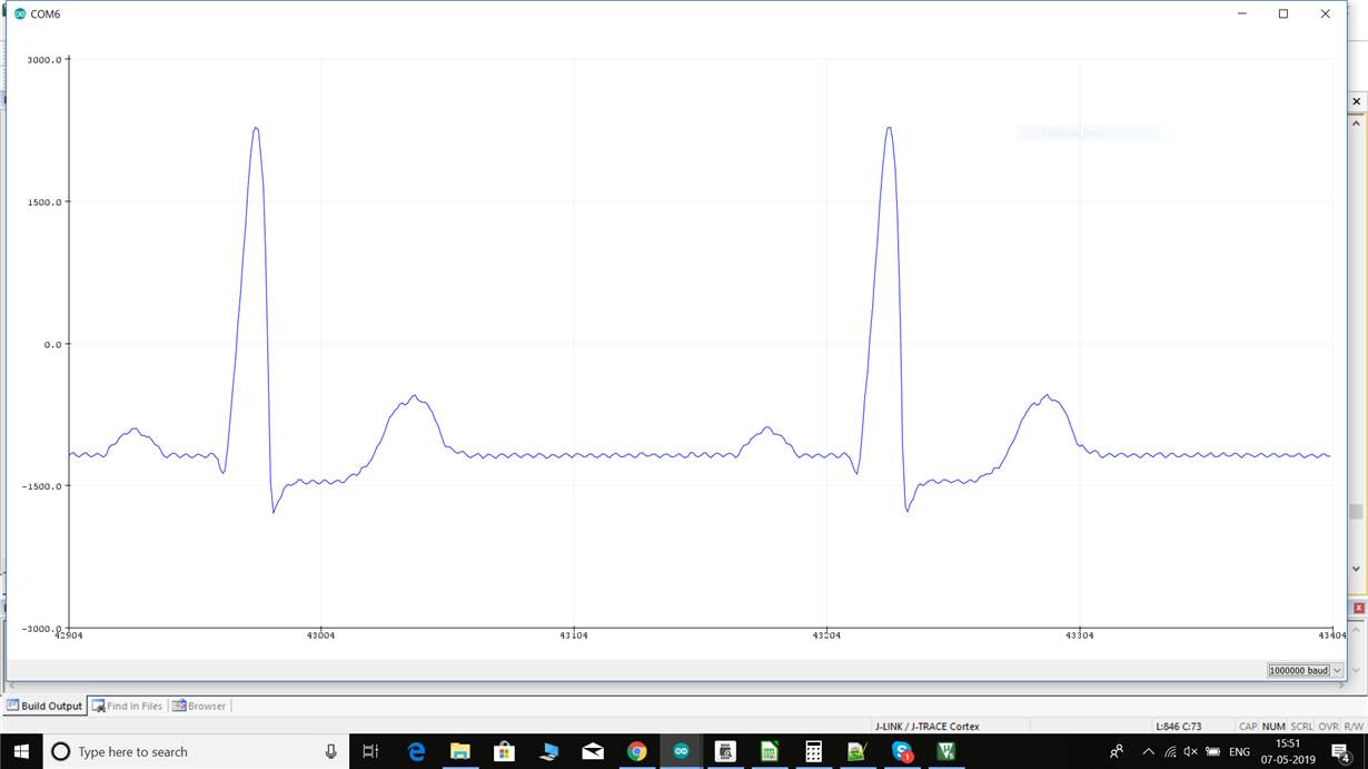
I am able to acquire the following waveform using my ADS1298R PDK by connecting a CARDIOSIM 2 simulator. However, I am getting this waveform only on Channel-2 and not on the others. The other channels don't have a valid ECG waveform even though I have configured them in a similar manner. I have tried multiple configurations and adjusting the gain, but it does not seem to make any difference. What can I do for the same? Also, on this waveform I am getting a 50Hz noise. I am using a power adapter connected to a 230V, 50Hz supply. Could it be eliminated by replacing the adapter with a battery pack? Or would I be required to use a notch filter for the same? 

Thanks.

  • ads1298 data.xlsI am also attaching for reference, the data on each channel.

  • Hi Sudarshan,

    With the information provided I cannot say what the issue is. Are the channels enabled in the registers? Can a signal from a signal generator be seen?

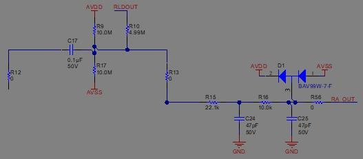
    As for the noise, using a battery will help - however it may not fix all of the issues. You may need to cancel the common-mode noise using the RLD output. If using the RLD output is not an option you have a few other options. Without a dedicated electrode to act as a driven right-leg bias, the analog inputs will need to be AC-coupled. This requires a series capacitor (i.e. 100 nF) followed by a resistor divider (i.e. 10MΩ) to set the common-mode to mid-supply. Low component tolerances should be used to maintain the highest possible CMRR.

    Alternatively, instead of using a resistor divider between the supplies, a single pull-up resistor connected to RLDOUT can be used. Reduce the resistor value by half to maintain the same high-pass filter cutoff frequency (i.e. 5MΩ). The advantage is that the RLD amplifier can still be used in this configuration to reduce the effect of the mismatch in the R-C low-pass filters.

  • Hi. I have configured all the channels exactly the same and I'm getting a test signal on all 8 channels. However, as it is observable on the Excel sheet attached above, my data on all channels except channel 2 is mostly noisy (Even though it might be a valid waveform post noise-filtering). I am unsure whether it is valid or not and whether or not I need to filter or observe if I have to change the configurations in any way. This is how I have configured the channels:

    uint8_t CH2[3] = {0x46,0x00, 0x10};
    uint8_t CH3[3] = {0x47,0x00, 0x10};
    uint8_t CH4[3] = {0x48,0x00,0x10};
    uint8_t CH5[3] = {0x49,0x00, 0x10};
    uint8_t CH6[3] = {0x4A,0x00,0x10};
    uint8_t CH7[3] = {0x4B,0x00, 0x10};
    uint8_t CH8[3] = {0x4C,0x00,0x10};
  • Hi Alex,
    I am now able to acquire data on all the 8 channels. I am currently working on the RLD and WCT portion. From what I understand, both RLD and WCT are the same signal (Average of RA, LA, LL). How do I go about using these in my board? Do i configure both these signals or just one?

  • Hi Sudarshan,

    The can be configured to be the same, but they are intended for different things. RLD is meant to cancel out the common-mode noise whereas WCT is meant to be a common point for 12 lead measurements.

    I recommend you view these videos: training.ti.com/how-measure-ecg-introduction-what-ecg
    Read this app note: www.ti.com/.../sbaa188.pdf
    and consult the datasheet sections on RLD and WCT. Additionally, the EVM user's guide may be helpful for a schematic example.
  • Thanks for the insight, I will go through this material.