This thread has been locked.

If you have a related question, please click the "Ask a related question" button in the top right corner. The newly created question will be automatically linked to this question.

ADS1298: Detection of Pacemaker circuits with ADS1298

Part Number: ADS1298
Other Parts Discussed in Thread: ADS1261

Dear All, 

Can i post some updates for the problem we faced with the ADS1298 regarding the detection of the pacemaker from the odd channels, which i have discussed it with you before in the topic with link http://e2e.ti.com/support/data-converters/f/73/t/841642.

To make the long story short, we were trying to detect the pacemaker pulse with the the smallest duration and amplitudes (equal and smaller than 10mV - 0.1ms), we were using the same circuit stated on the paper http://www.ti.com/lit/ug/tidub75/tidub75.pdf, but instead of using the SAR ADC ADS7042, we are using the ADS1261, because its higher sampling rate and it has 24-bit high precision ADC, it is needed on our design for the pace detection algorithms and other required functions.

Here is the schematics for the connection of the input stages of the ECG leads to the AFE, taking in your consideration that the PGA of the AFE is set to 6.


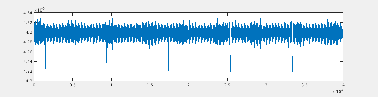
After using a noise-free environment to get rid of any unwanted noise, we can easily detect the pacemaker pulses from even channel with 2mv- 0.1ms, as you can from the following picture, this is the plotting for data taken from the pin (TESTP_PACE_OUT) by the ADS1261 without any digital filters, only the anti-aliasing low pass filter, the pacemaker pulses are so clear and can be detected easily by the microcontroller.

We still have problem in the detection in the pacemaker signals derived from the odd channels, it has a higher noise which cover the pacemaker pulses.

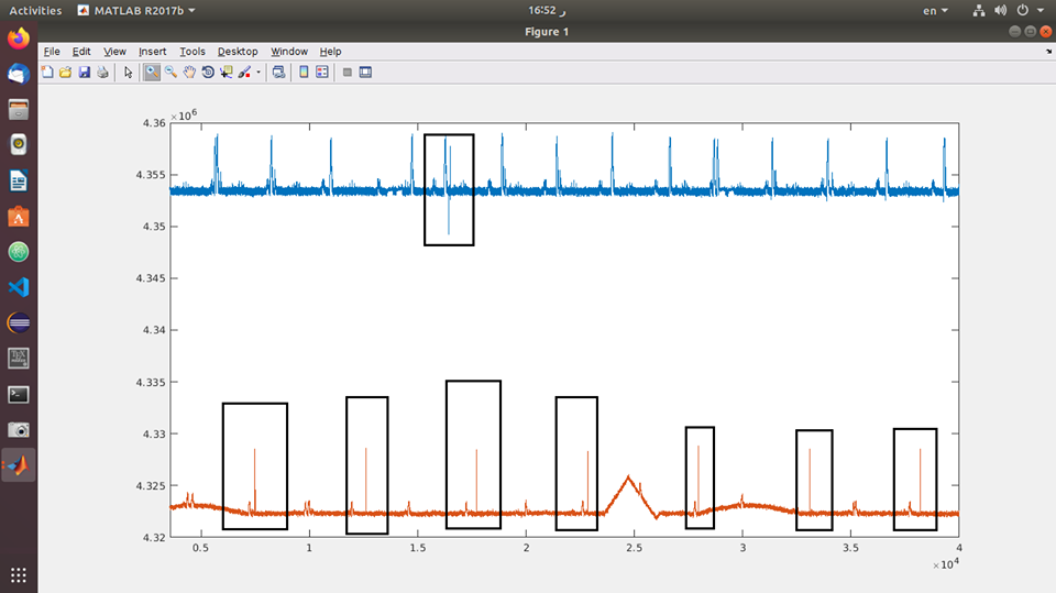
this is the signal derived from an analog channel, from the pin (TESTN_PACE_OUT), with 10mV - 0.1ms.


and this is the pacemaker signal with 50mv - 0.1us without any digital filters also.


We only want to know why the path of the odd channels contains more noise than the one with the even channels.


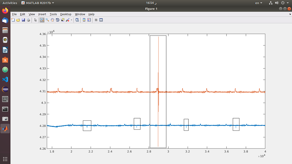
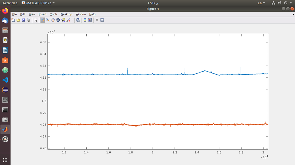
Also this a comparison for the two outputs together without any pacemaker signals, only the ECG outputs, the blue signal is derived from the odd channel, and the even signal is derived from the even channel.


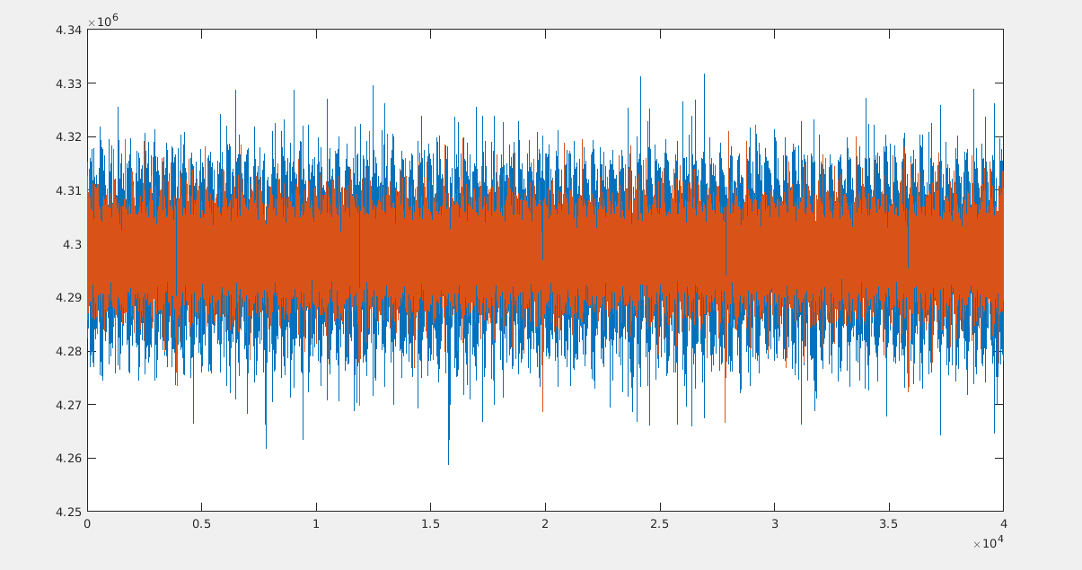
Is there any way to reduce this noise? and do you know any reason why this noise is appeared?

looking forward to your reply, and please don't hesitate to contact me if you have any further details.

  • Hi Ahmed,

    Thanks for the update.

    The data sheet only provides a typical 20uVrms noise for the pace amplifiers and there is no min/max spec, so this could easily vary within +/- one standard deviation of tested devices.

    Are you testing exactly the same electrode inputs to compare PACEE vs PACEO channels? I would test the same electrode pair on each pace channel, one at a time.

    What exactly do you mean by "without digital filters?" You cannot bypass the digital filter in the ADS1261. Additional filtering might be needed to average out the noise for both odd and even pace channels.

    Best regards,

  • Dear My Ryan,

    We were trying using the RA electrode, which is - as stated on the schematics - connected to both the even and odd channels, and the result is as stated in the main topic, and also this problem appeared with using other channels.

    but i have an update for you, after the conversion of the these captured signals in the frequency domain, the frequency of the noise is available on the range of 50 Hz and its harmonics, and also on the range the 4 kHz, but as stated on the datasheet, we know that the 4k is coming from the chopping frequency of the WCT amplifiers, so the problem still on the frequencies of the 50 Hz and its harmonics.

    The level of the noise on the 50Hz frequencies on the odd channels is larger than (approximately the double of) the even ones. 

    but after trying to remove any connections to the mains for the board and the simulator, we can get rid of 70% of the noise on the odd channels, but it still appears on the odd channels.

    Do you know what is the most optimum way to get rid of that 50Hz frequencies?

    I mean by "no digital filters", we don't use any digital filters on our side, the signal derived for the pace_out pins is captured / plotted without using any digital filters on them.

    Also, regarding the chest leads, the IEC criteria for pace detection refers for detecting pace on every lead individually, so we need to detect pace on the chest leads V1 to V6.

    As you can see on the schematics, V1 and the WCT are connected to Channel 8, and V6 and the WCT are connected to channel 7, so we adjust PACEE and PACEO for channel 6 and 7, and we could capture the pacemaker signals by this way, but in this case the frequency of the 50Hz appeared also with higher levels on the even channel than the odd one.

    Do you know the main reason for the appearing of these frequencies? or do you have any suggestions for removing them?

  • Hello Ahmed,

    I understand that RA is shared between IN2N and IN3N. However, the positive electrode is different for each channel: IN2P is connected to LA and IN3P is connected to LL. In order to compare the PACEE and PACEO channels, you would need to connect the same two electrodes to each channel: first, to the even channel, then to the odd channel, and observe the difference in signal and noise amplitude.

    It's helpful to know that the nature of this noise is generally n*50 Hz. I suspect that the limitation is coming from the CMRR in the signal path. Most of the degradation to CMRR in ECG applications comes from the mismatch of the signal chain components (i.e. passive R-C filters) as well as the difference in electrode contact impedance. The PGAs on each channel do not cancel any of the common-mode signal; in fact, they pass the common-mode through directly. However, the PACE amplifiers should remove most of the common-mode noise when they perform the differential-to-single-ended conversion. There could be some slight impedance differences between the PACEE and PACEO amplifier circuits that results in poor CMRR. I will have to discuss this with a designer to understand how well-matched the PACE circuits are expected to be.

    The best way to reduce and minimize 50-Hz noise is to suppress it at the source (i.e. on the body). This is primarily achieved by maximizing the gain of the RLD loop and by choosing very low tolerance signal chain components. You can also reduce the coupling by shielding the ECG cables and the PCB and driving that shield to the same common-mode as the what is seen by the body.

    Best regards,

  • Dear Ryan,

    I have an update for you, after the selection of two channels of Vs from the register, V1 (even) and V5 (odd), and plotting the signals 

    The following drawing is showing the Even V (700mV - 2ms ) signal in Blue vs. the Even LA (2mV - 0.1ms) signal in red.


    The following drawing is showing the odd V (700mV - 2ms ) signal in Red vs. the odd LL (2mV - 0.1ms) signal in Blue.

    The following drawing is showing the Even LA (2mV - 0.1ms ) signal in Blue vs. the Odd LL (2mV - 0.1ms) signal in red.

    as you can see the problem in the amplitude of the signal derived from the even V (700mV) is so small compared to the signal derived from the odd, that's why we can't get any pacemaker signals on the small range, because its output is so small compared to other signals, and this problem is not available on signals derived from the odd channels or any of the limb leads.

    I'm still looking for an answer to the question related to the pace amplifiers, is there any difference in there output or in their configuration? the datasheet shows no problem between them, but performing the tests on it shows these difference.

    And also to remove any confusions, we are using a SECG 4.0 whalteq simulator to derive these signals, because it has the ability to select an individual channel (lead) to perform the required tests stated by the IEC on it.

    looking forward to your reply.

  • Hello Ahmed,

    Thanks for the updates.

    Originally this question was about the difference is noise performance between the two PACE amplifiers. For that, our design team ran some CMRR simulations to analyze the distribution in CMRR performance. Based on Cadence spice simulation only, the mean CMRR of the PACE amplifiers is about 76 dB (84 dB - 8 dB due to 0.4 V/V amplifier gain). The spread is about +/- 20 dB (peak-to-peak). Therefore, the 0.1% resistor tolerance in the data sheet is actually closer to the worst-case scenario rather than the expected typical (0.1% = -60 dB). From this we can conclude that the CMRR of a given PACE channel alone is expected to be closer to 76 dB, but it's possible for there to be a noticeable difference between the two amplifiers in one device due to the spread. We have not characterized whether the performance differences are systematic in any way (i.e. Channel A -> PaceX is always worse than Channel B -> PaceY).

    I do not have a Walteq simulator, but I do have a Fluke medSim 300b that has pacer capability. I can try to reproduce this test setup on an EVM. Can you please share the complete ADC register settings used for these tests? The PACE register settings will change for each test, but the rest should remain consistent. Also, please confirm my understanding of the electrode inputs and pace amplitudes is correct as well:

    Figure 1:

      • (Blue) "Even V" = Channel 8 (V1 - WCT) to PACEE amplifier. Pace signal is 700 mV, 2 ms. Is this correct?
      • (Red) "Even LA" = Channel 2 (LA - RA) to PACEE amplifier. Pace signal is 2 mV, 0.1 ms. Is this correct?

    Figure 2:

      • (Red) "Odd V" = Channel 1 (V5 - WCT) to PACEO amplifier. Pace signal is 700 mV, 2 ms. Is this correct?
      • (Blue) "Odd LL" = Channel 3 (LL - RA) to PACEO amplifier. Pace signal is 2 mV, 0.1 ms. Is this correct?

    Figure 3:

      • (Blue) "Even LA" = Channel 2 (LA - RA) to PACEE amplifier. Pace signal is 2 mV, 0.1 ms. Is this correct? Is this correct?
      • (Red) "Odd LL" = Channel 3 (LL - RA) to PACEO amplifier. Pace signal is 2 mV, 0.1 ms. Is this correct?

    Best regards,

  • Dear Mr Ryan, 

    Thanks for this quick reply, 

    Regarding the 1st part on your reply, my apologies but i didn't get the conclusion of it, does that mean that one of the amplifiers has a higher noise than the other? i don't get quite right.

    Regarding the 2nd part, yes, you got the figures right, and the configuration is as the following:

    • PACE register is configured with value (0x1D) to get the pacemaker on Channels 8 and 5, and configured with value (0x03) to get the pacemaker on channels 2 and 3.

    • All the CHnSET registers are set to (0x00)
      • Normal operation,
      • PGA Gain of 6
      • Normal electrode input

    • CONFIG1 is set to (0x86)
      • High resolution mode with 500 SPS
      • Daisy pin is connected to the ground.
      • The internal oscillator clock is disabled

    • CONFIG2 is set to (0x02)
      • Test signals are not used.
      • WCT chopping scheme is variable.

    • CONFIG3 is set to (0xEE - 0b11101110)
      • RLD is connected.
      • RLD sense is enabled.
      • RLD buffer is enabled.
      • RLD signal is generated internally.
      • Reference voltage is 4V.
      • Enternal refernce buffer is enabled.

    • CONFIG4 is set to (0x02)
      • Lead-off comparator is enabled.
      • WCT to RLD connection is off.
      • Continuous mode is used.
      • No respiration is available.

    • WCT1 is set to (0x0B)
      • Channel 2 negative input connected to RA, and it's connected to channel 3 negative input through the hardware.
      • WCTA is powered-On.

    • WCT2 is set to (0xD4)
      • Channel 2 positive input is connected to LA.
      • Channel 3 positive input is connected to LL.
      • WCTB and WCTC are powered-On.

    Also i have a question regarding the polarity of the incoming pacemaker pulse, in case of the selection of a positive pacemaker signal, when selecting

    • LA, the pulse is positive.
    • LL, the pulse is negative.
    • RA, the pulse is negative.
    • Odd V, the pulse is positive.

    Is the polarity of the pulse related to the out of the pace pin or the channel of the ADC or both?

    Let me ask the question in another form, when LA is selected, which is connected to the positive differential part of an even channel, and captured from the output of positive PACE amplifier, it's a positive pulse, and vice versa when LL is selected, but why the output is different with RA and the Vs connected to the odd channels?

    Another question here, regarding the performing of the tests as stated on IEC 60601-2-25/27/47, the pacemaker is captured from an individual lead, and all the other wires must be connected to the RL.

    Looking forward to your reply, and please correct me if i made something wrong in the configuration.

  • Hello Ahmed,

    The point about the CMRR simulation was to say that it's possible for common-mode noise to become a differential noise at the output of the PACE amplifiers as the CMRR can vary. We don't have a firm conclusion that one PACE amplifier will be noisier than the others.

    There is a discrepancy in your register settings that conflicts with your previous post. Earlier, your plots indicated you were measuring "Even V" = Channel 8 (V1 - WCT) to PACEE amplifier and "Odd V" = Channel 1 (V5 - WCT) to PACEO amplifier. This would require programming the PACE register (15h) to 0x19 to select Channel 8 and Channel 1.

    Ahmed Sabry said:

    Also i have a question regarding the polarity of the incoming pacemaker pulse, in case of the selection of a positive pacemaker signal, when selecting

    • LA, the pulse is positive.
    • LL, the pulse is negative.
    • RA, the pulse is negative.
    • Odd V, the pulse is positive.

    The PGA is made up of two non-inverting amplifiers in an INA configuration, so each input pin on the device (INxP and INxN) connects to the non-inverting input of an amplifier. For INxP inputs, the output of the PGA connects to the non-inverting input of the PACE amplifiers. For INxN inputs, the output of the PGA connects to the inverting input of the PACE amplifiers. There should be no difference in the sign of the signal between the differential PGA output (measured by the ADC) and the singled-ended PACE output.

    Keep in mind that you are selecting the whole channel to connect to the PACE amplifiers - that is to say, you cannot select "only LA" or "only RA". When you select LA, you are also selecting RA and the PACEE amplifier output will be (LA - RA) x PGA gain x PACE gain + mid-supply.

    Best regards,