


Part Number: DAC38J84
Hi,
I am trying to generate an RF signal with the DAC38J84. My idea is to send constant IQ samples from the FPGA and use the complex mixer inside the DAC to generate the signal I*cos(x)+Q*sin(x) and output it using one of the four DACs in the chip.
In the next figure it is shown the JESD core used in the FPGA:
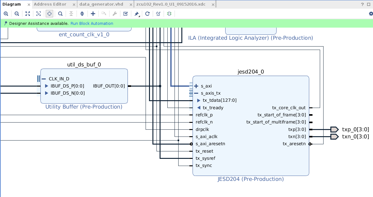
I configure this JESD core with:
- L = 4
- F = 2
- K = 1
- reference clock 122.88MHz
- Lane Rate 4.9152 Gbps
My first question is related to how IQ samples need to be placed in "tx_tdata".
I understand I have 32 bits per lane: lane_3 (tx_data(127..96)), lane_2 (tx_data(95..64)), lane_1 (tx_data(63..32), lane_0 (tx_data(31..0)).
I want to send two set of IQ samples to get 2 different RF signals, one in output DACA and one in output DACC. I am testing with I and Q constants (16 bits each). How the Is and Qs need to be placed in tx_data? Is the following correct?tx_data = Qch2_2 & Qch2_1 & Ich2_2 & Ich2_1 & Qch1_2 & Qch1_1 & Ich1_2 & Ich1_1;
so: lane_3 = Qch2_2 & Qch2_1
lane_2 = Ich2_2 & Ich2_1
lane_1 = Qch1_2 & Qch1_1
lane_0 = Ich2_1 & Ich1_1
with "IchX_n" or "QchX_n" where "X" indicates the RF signal and "n" indicates the sample index in time. This way, if I want to send I and Q constants I set tx_data for example as:
tx_data = x"1111" & x"1111" & x"2222" & x"2222" & x"3333" & x"3333" & x"4444" & x"4444";
In the DAC side I have the following configuration:


In the next figure I draw what I expected to happend:


I think I have not understood how I and Q samples need to be placed in tx_data.
when I set tx_data = x"88887777666655554444333322221111" I get in DACA the following:
(I the next figures, the mixer is disabled)

when I set tx_data = x"00008888000066660000444400002222" I get in DACA the following:

and for tx_data = x"3FFF3FFF3FFF3FFF3FFF3FFF3FFF3FFF"
tx_data = x"3FFF00003FFF00003FFF00003FFF0000"
tx_data = x"00003FFF00003FFF00003FFF00003FFF"
tx_data = x"80007000600050004000300020001000"
I always get flat 0 at the output...
Any help about the configuration and/or how I have to place my IQ samples in tx_data would be great.
Thanks in advance,
Juan.

