This thread has been locked.

If you have a related question, please click the "Ask a related question" button in the top right corner. The newly created question will be automatically linked to this question.

ADS1299: The correct way to set up BIASINV

Part Number: ADS1299

Hi, 

I would like to build a single-ended 4 channel EEG measurement system with a bias electrode. I'm confused about the function of  BIASINV.

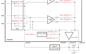
In Figure 34 in the datasheet, BIASOUT and BIASINV is connected with an RC filter, and BIASOUT is connected to BIASIN by feedthrough.

However, I also find some open source projects that implement BIAS I/Os differently, both of the projects below do not connect BIASINV with BIASOUT.
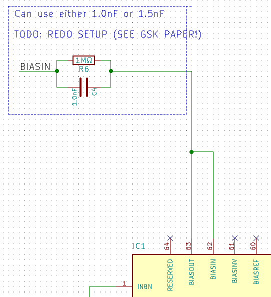
 https://github.com/MusaMahmood/KiCAD-EEG-INA828-nRF52
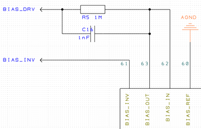
 https://github.com/OpenBCI/V3_Hardware_Design_Files

Should I follow the datasheet to connect BIASINV to BIASOUT with an RC filter? Or can I just float the BIASINV?

  • Hello,

    Thank you for your post.

    The BIAS amplifier requires some feedback in order to operate in a closed-loop configuration. In the data sheet and ADS1299EEGFE-PDK User Guide, we are showing an example circuit which provides local feedback and limits the closed-loop bandwidth to about 106 Hz. This ensure stability as the amplifier drives the common-mode voltage to the body.

    Other implementations of the BIAS amplifier rely on the internal the connections from PGA outputs to BIASINV to close the feedback loop. In this case, the body, cable imepdances and parasitics, and input signal chain are all part of the BIAS amplifier feedback loop. This type of circuit must be analyzed carefully to ensure the BIAS amplifier remains stable during normal operation.

    I suggest starting with the data sheet circuit.

    Best regards,

  • Hi,

    The BIAS section of the circuit is meant to establish a common-mode voltage on the patient, such that the incoming signals being read from the electrodes will be within the common-mode range of the PGA. Additionally, this allows the inputs to cancel-out the common-mode noise that typically couples onto the patient from the main power lines. 

    There are a lot of ways to accomplish this, and it depends on each individual end application. 

    I suggest you take a look at the BIOFAQ located here: https://e2e.ti.com/support/data-converters/f/73/p/772058/2855202

    You can also search the forum for additional implementations. Good luck!  

  • Thank you for your help!