This thread has been locked.
If you have a related question, please click the "Ask a related question" button in the top right corner. The newly created question will be automatically linked to this question.
Hello,
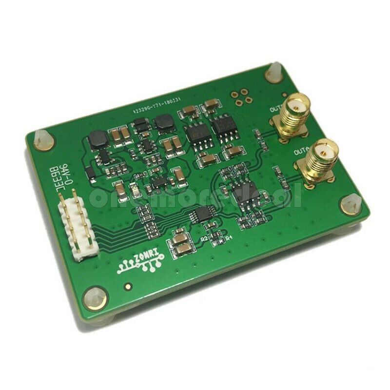
I bought a DAC8563 breakout for bipolar analog output. I am trying to control it with arduino uno but i couldn't manage it.
Pins;
Arduino pin 13 ---- SCLK pin
Arduino pin 11 ---- DIN pin
Arduino pin 10 ---- SYNC pin
LDAC and CLR pins are at GND.
Arduino code;
#include <SPI.h>
const int syncpin = 10;
int command;
void setup() {
// put your setup code here, to run once:
pinMode(syncpin, OUTPUT);
digitalWrite(syncpin, HIGH);
Serial.begin(9600);
SPI.begin;
SPI.beginTransaction(SPISettings(1000000, MSBFIRST,SPI_MODE1));
}
void loop() {
// put your main code here, to run repeatedly:
if (Serial.available()){
command = Serial.read();
if (command == '1'){
digitalWrite(syncpin,LOW);
SPI.transfer(0x30);
SPI.transfer(0x00);
SPI.transfer(0x03);
digitalWrite(syncpin,HIGH);
Serial.println("LDAC disabled");
}
else if (command == '2'){
digitalWrite(syncpin,LOW);
SPI.transfer(0x17);
SPI.transfer(0xFF);
SPI.transfer(0xFF);
digitalWrite(syncpin,HIGH);
Serial.println("DAC registired");
}
else if (command == '3'){
digitalWrite(syncpin,LOW);
SPI.transfer(0x27);
SPI.transfer(0x00);
SPI.transfer(0x03);
digitalWrite(syncpin,HIGH);
Serial.println("DAC powered up");
}
}
}
I couldnt take any response from my output. Any advice?
Thanks.
Taha,
Today has been a busy day for us in the DAC group with some folks out of office as well, so I apologize for the delay.
I will look into your topic more tomorrow, but in the meanwhile it is most helpful to see what is actually happening on the bus. So, if you can grab oscilloscope captures of the SPI transaction on SCLK, DIN, and SYNC relative to one another that would be a helpful addition.
If you have a schematic or reference material for the DAC8563 board as well, or even a link, that would help too.
Hello Kevin,
Thanks for your attention. I don't have an oscilloscope so sorry to i can't upload any captures.
Hello,
It is imperative that you have the ability to judge what is physically appearing on the bus in order to debug this. I will spend some time either this weekend or early next week familiarizing with the board you've linked us to to try to understand your connections.
Hello,
I found an example for communicate two arduinos. I tried and it worked normally. I can be sure that spi of arduino is working normally but i am not sure if my settings are wrong or something else. I am waiting for news.
Have a good weekend.
Is it safe to assume that the SPI_MODE1 alias in your code means SCLK idles low and the falling edge is the latching edge?
According to the datasheet CLR is an edge sensitive signal, however I am curious if your results would be different with CLR tied high instead of to GND.
I would suggest double-checking your board-to-board connections, particularly ensuring that you have connected GND between the two boards or all of the SPI signals will be a floating potentials. Presumably this is the case if you had success with the two Adruino boards.
Hello Kevin,
I choose spi mode from datasheet of dac856x. My board is supplying from arduino so grounds are same.
I found a library for DAC8562 (https://github.com/k164v/DAC8562) and i am able to communicate with my board so far. Just i have to change some configurations for DAC8563.
Thanks for help.
Best regards.